|
| 93_eb_fairmont |
|
|||
|
Well yeah you can take out the 18 ohm resistor all that does is give the gearbox something to go back to otherwise it goes into limp home mode. Working on figuring out what resistors you need mate, bear with me.
_________________ How many bears could Bear Grylls grill if Bear Grylls could grill bears? |
|||
| Top | |
|||
| wrexed03 |
|
||
|
No probs looking forward to an update. Keen to do this.
|
||
| Top | |
||
| wrexed03 |
|
||
|
Ok here is an update. I had a play with the unit this arvo. Finally success.
What i did is found some old pc powersupplys that i was going to bin ripped them apart and found some 5 ohm resistors. I added them to the circuit where the adjustable pot lives. What this has done is increase resistance up to 25ohms. Fitted it to the vehicle and the thing shifts harder and chirps the wheels without much effort and not heaps of throttle. (Turn it off in the wet Will go for a drive to jaycar tomorrow and have a look if they have anything in this range and do this properly. Big thankyou to 93_eb_fairmont for posting the schematic and the tips along the way. Another thank you to the police officer who didnt pull me over whilst i was testing. I didnt see him behind me lol... Regards |
||
| Top | |
||
| 93_eb_fairmont |
|
|||
|
Champion of the year award goes to wrexed03 for testing it out and finally getting it working. I knew it was gonna be those pins and I knew itd be that pot causing problems but good on you for taking the initiative and getting it working. Let us know if you get a pot that does it right and post up the part number.
_________________ How many bears could Bear Grylls grill if Bear Grylls could grill bears? |
|||
| Top | |
|||
| wrexed03 |
|
||
|
No probs will post once i find an adjustable pot that will do the job.
Regards |
||
| Top | |
||
| wrexed03 |
|
||
|
Ok fellas went to Jaycar this morning they dont have a larger potentiometer 20-30ohms should do the job to make it adjustable.
What you can do if you want to make this kit is replace the potentiometer with 2 or 3 10ohm 10W resistors and connect them end to end. I am running 3 of these. The shifts are firm and it chirps the tyres no probs in pwr mode. In Econ mode its still firm but not as agressive due to the earlier shifting. You can turn the unit off using the switch as well if it gets too much for you. Follow the diagram above on the basis of using the resistors connected end to end instead of the potentiometer. Dont forget to turn it off when it rains. There is a very good chance that the back of the car will slide because of the firmness. Parts list i used is as follows. 1 x 18 OHM 10 W RESISTOR Cat No. RP3975 3 x 10 OHM 10 W RESISTOR Cat No. RR3352 1 x DPDT Heavy Duty Toggle Switch Cat No. ST0575 1 x Black Enclosure to house the components Cat No. HB6013 You can choose your own but make note the resistors in the kit are large. Finally if you attempt this and you mess up your car i will not be responsible. Resposibility falls back to the owner of the vehicle. The above has worked on my 1997 NL 5.0 Fairlane i would expect it to work on other E series V8's which use a TCM under the dash. Best Regards Wrexed03 |
||
| Top | |
||
| dylanfh |
|
||
|
Any chance of putting up a diagram with this setup?.
|
||
| Top | |
||
| wrexed03 |
|
||
|
See page 1 replace the pot with resistors. Just solder them together. Two wires that go to the pot now go to the resistors you soldered together. (Resistors should be soldered end to end).
Hope it makes sense. |
||
| Top | |
||
| dylanfh |
|
||
|
wrexed03 wrote: See page 1 replace the pot with resistors. Just solder them together. Two wires that go to the pot now go to the resistors you soldered together. (Resistors should be soldered end to end). Hope it makes sense. First of all sorry for playing around with the original diagram. So is this how it goes?.(excuse the rough job). 
|
||
| Top | |
||
| 93_eb_fairmont |
|
|||
|
Yes, they will look like this
---[|||||]------[|||||]------[|||||]--- End to end - ie: in series. No it doesnt matter which way around they go. Yes youve got the right idea with your diagram. Sorry I havent been more pro active but I just cant be bothered because people are still starting new threads about it instead of searching. Good luck and tell us what car you are putting it on
_________________ How many bears could Bear Grylls grill if Bear Grylls could grill bears? |
|||
| Top | |
|||
| dylanfh |
|
||
|
Thanks,so just to clear things up,2 wires go to 1 end of the 3 joined resistors and 1 goes to the other end?.So this will kind of make it like a 2 stage setup?.It will be going into a 5.0 EF Ghia in about 2 days.If ive got the wiring idea of it ill let everyone know how it goes.
|
||
| Top | |
||
| 93_eb_fairmont |
|
|||
|
No it isnt a 2 stage setup, in order for a resistor to resist, electricity has to enter one end and exit the other. What you are going is going to be an on/off setup. If I were you I wouldnt put the LED in either, just to keep it simple and easy to mount so its just 1 switch and 3 wires. Conduit works well for stuffing the resistors into and then just tape it all up.
Yes, one wire on one end of the joined resisotres, 2 on the other. While youre at jaycar ask him if he's got any adjustable pots to do the same job itll be a lot simpler to wire but a bit more expensive but hen youll have a pot
_________________ How many bears could Bear Grylls grill if Bear Grylls could grill bears? |
|||
| Top | |
|||
| dylanfh |
|
||
|
Sorry for all the questions,dont want to stuff it up.
can i use as in both these diagrams or only 1 (top or bottom diagram?.). Ive tidied up the pic a bit better than before. 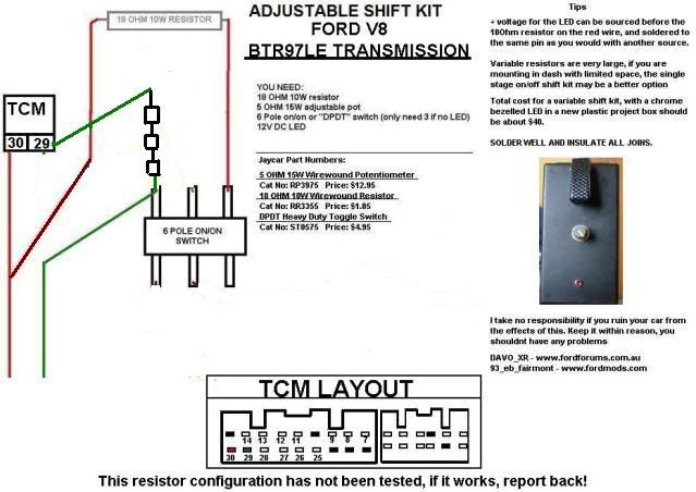 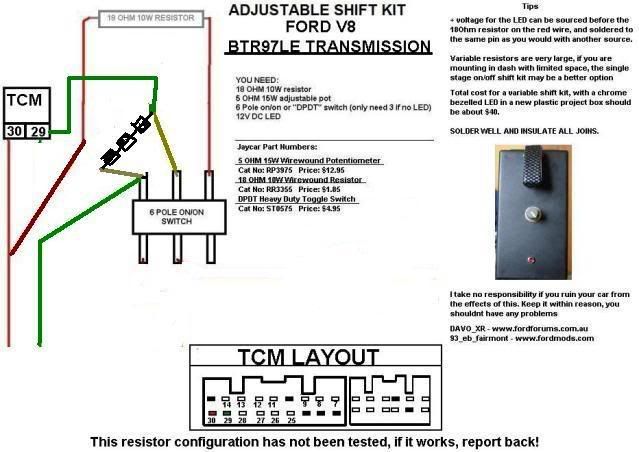
|
||
| Top | |
||
| slywog |
|
||
|
have you sorted the wiring out for the au v8 trans shift kit yet ????? if so whats the numbers ?
|
||
| Top | |
||
| ed5speeddanny |
|
||
|
Tried it today without switch kept going into limp home if resistance value was higher in pin 30 than the resistance in 29. Now just going to try having 25 ohm in 29 and 18 ohm in 30.
|
||
| Top | |
||
| Who is online |
|---|
Users browsing this forum: No registered users and 7 guests |
