|
| shooter |
|
||
|
Cheers mate. Yeah i may start a build thread to help others.
I have had one on boosted falcon to from a past build on this same car. Was building a sohc turbo at one stage. But may start one in here once i get the ba tomorrow |
||
| Top | |
||
| GrannyFalcon82 |
|
|||
|
BA cluster conversion update 1 - Some useful information ( use at own risk )
Here now, I have information regarding the use of a BA cluster into a boxcar ( EA - ED ) EF - EL and other various models will differ slightly in what sensors are useful. While there may be various ways to go about this mod, Johnny has inspired me to use an MDF board ( 12mm thick ) The difficulty isn't very so, indeed the average joe will be able to follow through with a bit of patience and " open mind-ness " The tools I've used for the making of said MDF adapter board : Jigsaw ( With a clean cutting, curve purpose blade ) Drill ( For Jigsaw shortcuts ) Pencil / P marker Ruler Strong work bench G clamp(s?) Patience ( Good eye for best precision ) Phillips head screw driver ( thin ) Tools used for making of wiring adapter : Soldering station 60 / 40 solder Heatshrink Cutting pliers Wire strippers Lighter Tape Good planning Lack of shaky hands ( You may struggle ) Solder sucker As once can see, the cluster fits nicely. While I may not be the most precise jigsaw operator, it still seems somewhat decent... Planning to paint the MDF adapter Matt black ( The lack of a glossy paint is best in this scenario )  Anyhow, lets get started... Start by removing the BA cluster outer housings, as one only needs the BA cluster housing itself, fascia cover and gauges, the fascia cover should be remove - able. Once this has been achieved, the fascia cover will need to be removed, as one must trace it on the MDF board. Grab the old boxcar cluster, disassemble the housing until the front plexiglass has been removed and the internal gauges gutted. The white housing will need to be traced onto the MDF board ( open end ). Once the old boxcar white cluster housing has been traced onto the MDF board ( open end ) One may proceed to trace the BA fascia cover into the center of the previous trace on the MDF board. This is best achieved if the BA fascia cover is turned upside down, note that the MDF board adapter needs to enclose around the black parts of the BA fascia to look neat ( Refer to pics on this page ) Make sure to include the speedometer / tachometer slight circular bulge at each top side. This may take a few attempts to get right. Have the markings be clear and bold, cut out the trace one has made ( Cut out the center part first, otherwise one will have a bad time ) Put the fascia cover back onto the BA cluster, slide the BA cluster underneath the cut out MDF board. Check that it appears to be neat and tidy, make necessary adjustments to the MDF cutout or simply start again ( Took me 3 attempts ) If one is happy with the center cutout, proceed to cut out the white housing trace that was made and fasten the BA cluster to the MDF cutout ( Take ones time with this, as one can see in the photo I've used many small screws, once loose it becomes slightly adjustable. Pilot holes will need to be drilled otherwise one risks cracking said MDF board ). 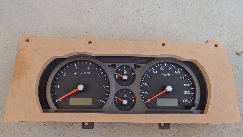  The boxcar plexiglass cover will need some modifications. Firstly the old warning lamp separator bar should be cut out ( be careful not to nick the plexiglass ) Once this has been removed, one will notice that the bottom edge of said cover isn't flat. The bottom edge becomes deeper at the bottom towards where the warning lamps were, one can flatten this edge therefore it will sit flush on the MDF board, and the trip button won't have to be extended ( Beware, this is risky and also bad for ones health as black plastic will be going everywhere ) 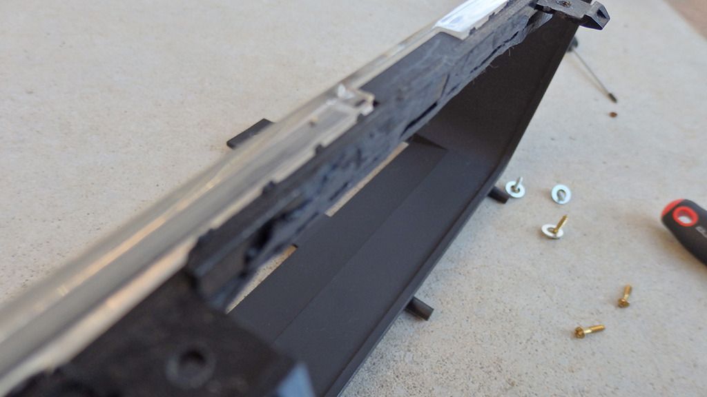 I Also removed the plexiglass piece on the top of the housing ( unsightly and seemed to be a pain ). Proceed to place the modified housing onto the MDF board and get the bottom four tabs to sit flush with bottom of MDF board. Trace around the upper four cylindrical points. These will be drilled out as said cylindrical points will drop into the top of board, thus becoming stronger. Once dropped in, fasten down with screws and washers on the other side. One will notice the trip bar faults on the plexiglass, mark the point and drill it out ( if using metal drill bit, try to use reverse throttling slowly, otherwise once that drill bit " bites " it will crack the plexiglass, that would be a very bad day ) The bottom of the cover should now slide down / in, whilst holding the cover down, drill through the tabs and into MDF board. These screws in said tabs will anchor the cover from springing back up again. 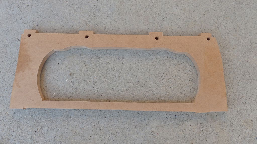 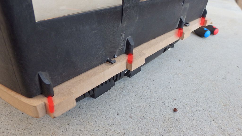 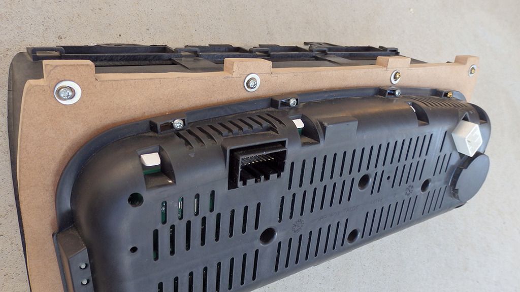  Saw off the MDF two bottom tabs ( They'll foul on the dash ) Test fit the new cluster into the car, making sure everything lines up and sits properly. For the most part, it's finished, one must decide what to do in terms of painting / sanding, in my case I've chosen to go with matt black as it dries a dark gray. Now onto the wiring! Bare with me here. ( This was the easiest, funnest part  On the old boxcar, white housing, the main PCB should be fastened to the back, remove this. Remove the screws that fasten the 12 Pin and 16 Pin joint female connector. Get out the soldering iron / solder sucker and flip the board over. Proceed to remove all solder joins that hold the female connector to the board ( depending on condition of board and solder, may take a while ) Once the female connector has been removed, stare at the black boxcar female connector side and have the upper tabs facing upwards. Refer to the diagram for pin numbers ( Don't make the mistake of looking at the male connectors the same way, turn the male connectors around and count the pins ). 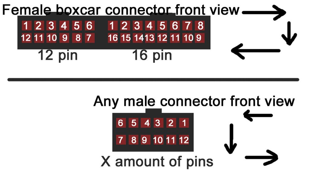 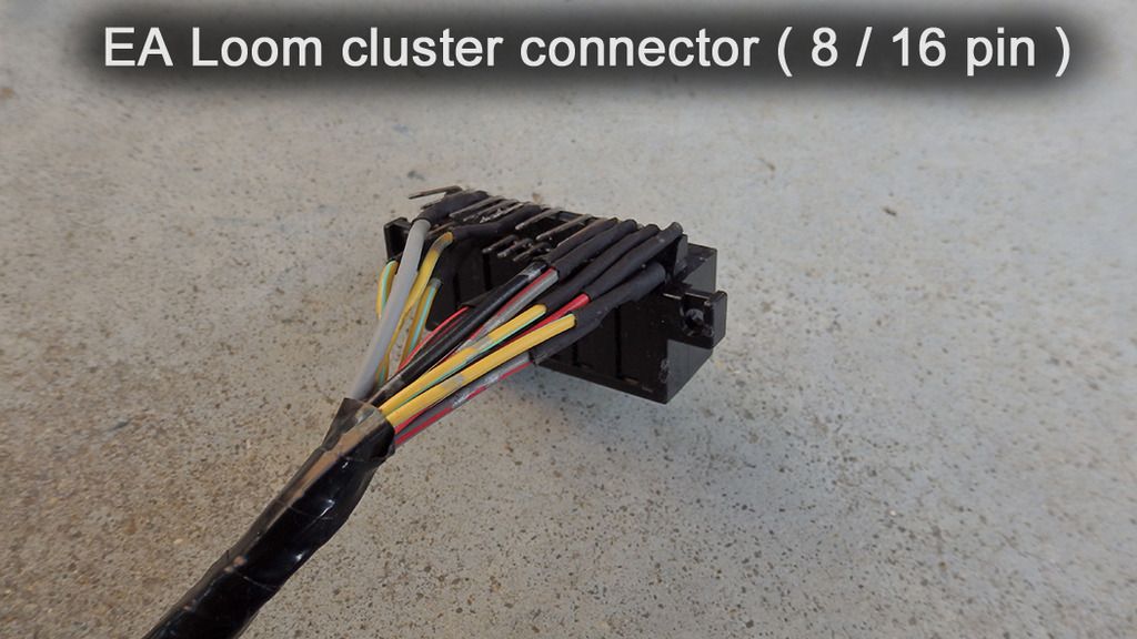 Grab the BA 20 pin and BA 8 pin male connectors, strip all of the wires in prep for joining to the female boxcar connector. One should decide how long they want their 20 or so wires ( This wiring adapter will branch off into two as the BA connectors are on either side of the cluster housing, so make sure it will reach to either side of the BA cluster without stressing / bending the pins on the boxcar female connector). If one has different color wiring, plan which color wire should go to what pin to ones own liking. 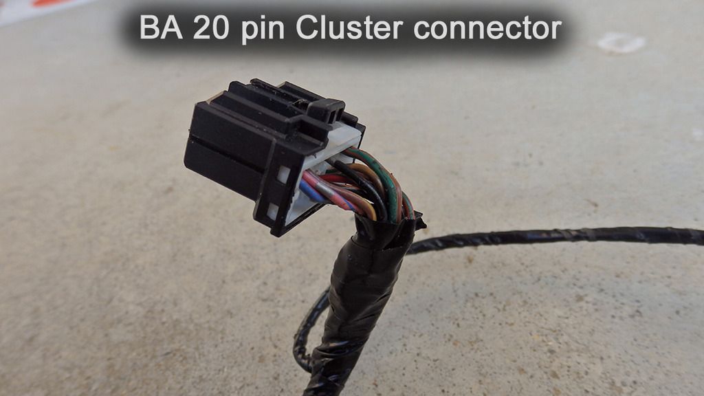 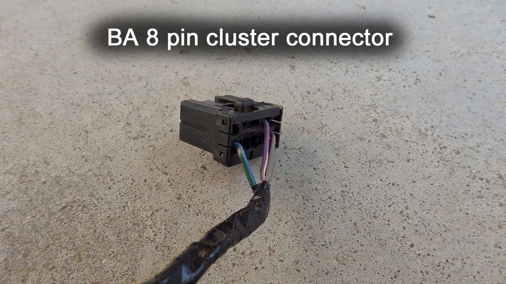 Here's a list of the wiring connections that I've made from the female boxcar connector, to each of the BA male connectors. Note that the connectors relate to pin count as such: " - " means " to " BA 20 ( 20 pin male connector ) BA 8 ( 8 pin male connector ) EA 12 ( 12 pin female connector ) EA 16 ( 16 pin female connector ) Here's that list : BA 20 - EA 12 wiring Pin 6 to pin 4 GROUND Pin 1 to pin 1 ILLUMINATION Pin 9 to pin 12 HIGH BEAM Pin 10 to pin 2 PARK LAMP Pin 16 to pin 9 BATTERY + ___________________________ BA 20 - EA 16 wiring Pin 13 to PIN 2 FUEL LEVEL Pin 12 to pin 12 HANDBRAKE LIGHT Pin 15 to pin 6 IGNITION Pin 2 CAN LO to obd2 can lo Pin 3 CAN HI to obd2 can hi ______________________________ BA 8 - EA 16 wiring pin 2 to pin 13 BRAKE FAIL ______________________________ BA 8 - EA 12 wiring Pin 8 to pin 3 LEFT INDICATOR Pin 4 to pin 11 RIGHT INDICATOR ______________________________ EA 16 wiring Pin 7 to Pin 15 Speedo transducer power source ( not recommended to pump 12v into vss, if one can, try to reduce the voltage with a resistor or other various, more efficient methods to 5 - 8v, otherwise do so at ones own risk ) _______________________________ Take time and care when soldering onto the female boxcar connector, don't bridge pins and make sure all pins are provided with heatshrink. All connections listed are what i've had available, I'm happy with the results, ones may vary if one doesn't pay attention. If this is being done on an EF - EL, the same logic can be applied just make sure one knows what pins are what on the EF - EL female connector(s?) 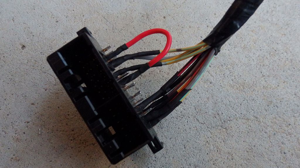 Test the adapter, if there's an issue, go back over the wiring connections and make sure one hasn't stuffed up ( eg. Wiring pin 15 on a male connector, while thinking one can count the pins the same as the front of a female connector from said front angle ) If the issue appears to be somewhat irresolvable, PM me for further assistance. Most likely user error. Note that I've yet to connect the left LCD cycle switch to anything, if done, an update will follow. Will update at a later point, eyes and fingers are tired as of this point in time
_________________ Rolling around with a Barra 182 - equipped 1988 EA falcon |
|||
| Top | |
|||
| GrannyFalcon82 |
|
|||
|
700x test
aaaaaaaaaaaaaaaaaaaaaaaaaaaaaaaaaaaaaaaaaaaaaaaaaaaaaaaaaaaaaaaaaaaaaaaaaaaaaaaaaaaaa1aaaaaaaaaaaaaaaaaaaaaaaaaaaaaaaaaaaaaaaaaaaaaaaaaaaaaaaaaaaaaaaaaaaaaaaaaaaaaaaaaaaaa2 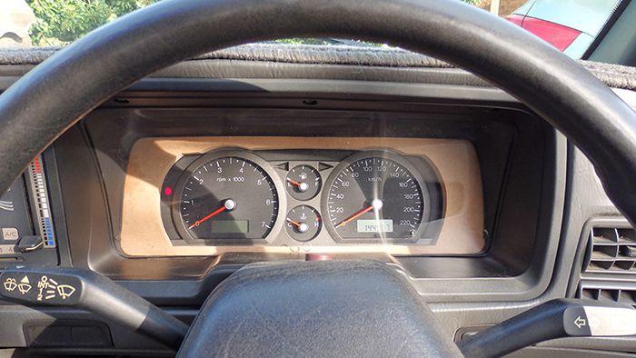
_________________ Rolling around with a Barra 182 - equipped 1988 EA falcon |
|||
| Top | |
|||
| GrannyFalcon82 |
|
|||
|
BA cluster conversion update 1 - Some useful information, MDF credit to JohnnyeHCF
Here now, I have information regarding the use of a BA cluster into a boxcar ( EA - ED ) EF - EL and other various models will differ slightly in what sensors are useful. While there may be various ways to go about this mod, Johnny has inspired me to use an MDF board ( 12mm thick ) The difficulty isn't very so, indeed the average joe will be able to follow through with a bit of patience and " open mind-ness " The tools I've used for the making of said MDF adapter board : Jigsaw ( With a clean cutting, curve purpose blade ) Drill ( For Jigsaw shortcuts ) Pencil / P marker Ruler Strong work bench G clamp(s?) Patience ( Good eye for best precision ) Phillips head screw driver ( thin ) Tools used for making of wiring adapter : Soldering station 60 / 40 solder Heatshrink Cutting pliers Wire strippers Lighter Tape Good planning Lack of shaky hands ( You may struggle ) Solder sucker As once can see, the cluster fits nicely. While I may not be the most precise jigsaw operator, it still seems somewhat decent... Planning to paint the MDF adapter Matt black ( The lack of a glossy paint is best in this scenario ) 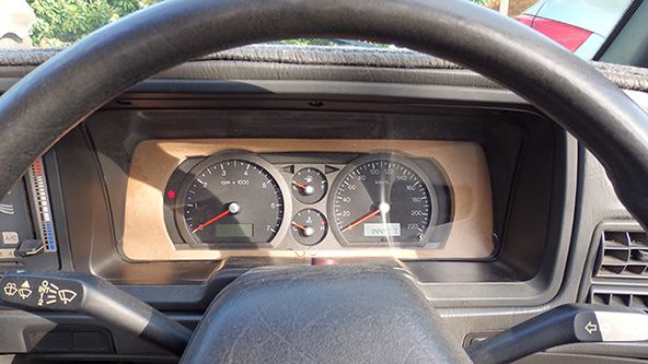 Anyhow, lets get started... Start by removing the BA cluster outer housings, as one only needs the BA cluster housing itself, fascia cover and gauges, the fascia cover should be remove - able. Once this has been achieved, the fascia cover will need to be removed, as one must trace it on the MDF board. Grab the old boxcar cluster, disassemble the housing until the front plexiglass has been removed and the internal gauges gutted. The white housing will need to be traced onto the MDF board ( open end ). Once the old boxcar white cluster housing has been traced onto the MDF board ( open end ) One may proceed to trace the BA fascia cover into the center of the previous trace on the MDF board. This is best achieved if the BA fascia cover is turned upside down, note that the MDF board adapter needs to enclose around the black parts of the BA fascia to look neat ( Refer to pics on this page ) Make sure to include the speedometer / tachometer slight circular bulge at each top side. This may take a few attempts to get right. Have the markings be clear and bold, cut out the trace one has made ( Cut out the center part first, otherwise one will have a bad time ) Put the fascia cover back onto the BA cluster, slide the BA cluster underneath the cut out MDF board. Check that it appears to be neat and tidy, make necessary adjustments to the MDF cutout or simply start again ( Took me 3 attempts ) If one is happy with the center cutout, proceed to cut out the white housing trace that was made and fasten the BA cluster to the MDF cutout ( Take ones time with this, as one can see in the photo I've used many small screws, once loose it becomes slightly adjustable. Pilot holes will need to be drilled otherwise one risks cracking said MDF board ). 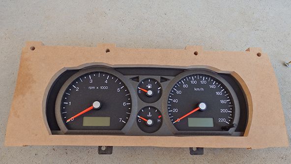 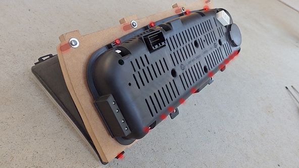 The boxcar plexiglass cover will need some modifications. Firstly the old warning lamp separator bar should be cut out ( be careful not to nick the plexiglass ) Once this has been removed, one will notice that the bottom edge of said cover isn't flat. The bottom edge becomes deeper at the bottom towards where the warning lamps were, one can flatten this edge therefore it will sit flush on the MDF board, and the trip button won't have to be extended ( Beware, this is risky and also bad for ones health as black plastic will be going everywhere )  I Also removed the plexiglass piece on the top of the housing ( unsightly and seemed to be a pain ). Proceed to place the modified housing onto the MDF board and get the bottom four tabs to sit flush with bottom of MDF board. Trace around the upper four cylindrical points. These will be drilled out as said cylindrical points will drop into the top of board, thus becoming stronger. Once dropped in, fasten down with screws and washers on the other side. One will notice the trip bar faults on the plexiglass, mark the point and drill it out ( if using metal drill bit, try to use reverse throttling slowly, otherwise once that drill bit " bites " it will crack the plexiglass, that would be a very bad day ) The bottom of the cover should now slide down / in, whilst holding the cover down, drill through the tabs and into MDF board. These screws in said tabs will anchor the cover from springing back up again. 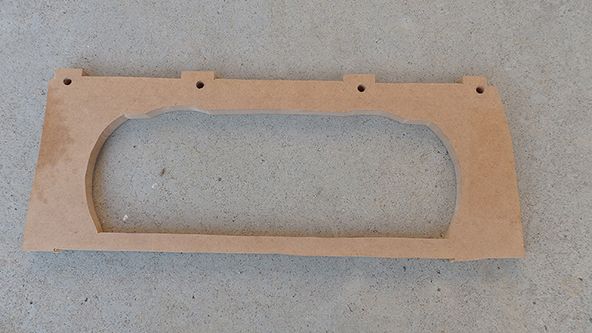  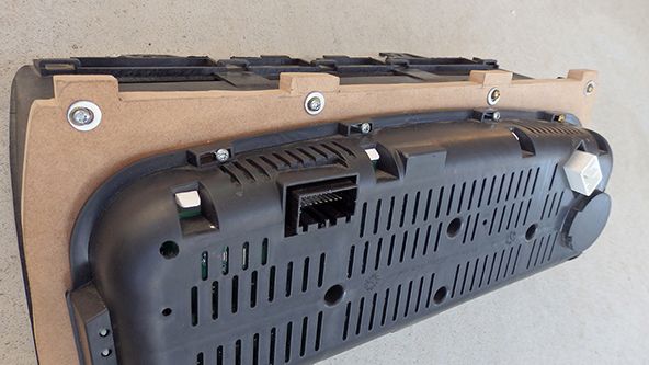 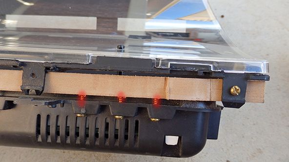 Saw off the MDF two bottom tabs ( They'll foul on the dash ) Test fit the new cluster into the car, making sure everything lines up and sits properly. For the most part, it's finished, one must decide what to do in terms of painting / sanding, in my case I've chosen to go with matt black as it dries a dark gray. Now onto the wiring! Bare with me here. ( This was the easiest, funnest part 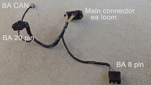 On the old boxcar, white housing, the main PCB should be fastened to the back, remove this. Remove the screws that fasten the 12 Pin and 16 Pin joint female connector. Get out the soldering iron / solder sucker and flip the board over. Proceed to remove all solder joins that hold the female connector to the board ( depending on condition of board and solder, may take a while ) Once the female connector has been removed, stare at the black boxcar female connector side and have the upper tabs facing upwards. Refer to the diagram for pin numbers ( Don't make the mistake of looking at the male connectors the same way, turn the male connectors around and count the pins ). 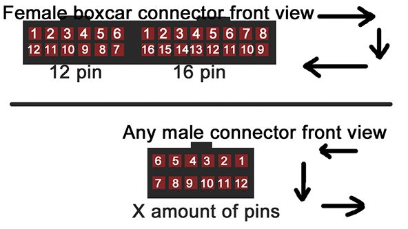 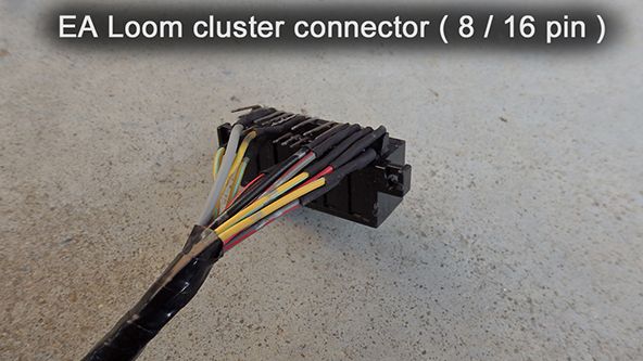 Grab the BA 20 pin and BA 8 pin male connectors, strip all of the wires in prep for joining to the female boxcar connector. One should decide how long they want their 20 or so wires ( This wiring adapter will branch off into two as the BA connectors are on either side of the cluster housing, so make sure it will reach to either side of the BA cluster without stressing / bending the pins on the boxcar female connector). If one has different color wiring, plan which color wire should go to what pin to ones own liking. 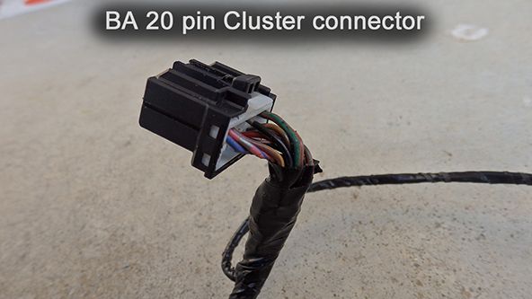  Here's a list of the wiring connections that I've made from the female boxcar connector, to each of the BA male connectors. Note that the connectors relate to pin count as such: " - " means " to " BA 20 ( 20 pin male connector ) BA 8 ( 8 pin male connector ) EA 12 ( 12 pin female connector ) EA 16 ( 16 pin female connector ) Here's that list : BA 20 - EA 12 wiring Pin 6 to pin 4 GROUND Pin 1 to pin 1 ILLUMINATION Pin 9 to pin 12 HIGH BEAM Pin 10 to pin 2 PARK LAMP Pin 16 to pin 9 BATTERY + ___________________________ BA 20 - EA 16 wiring Pin 13 to PIN 2 FUEL LEVEL Pin 12 to pin 12 HANDBRAKE LIGHT Pin 15 to pin 6 IGNITION Pin 2 CAN LO to obd2 can lo Pin 3 CAN HI to obd2 can hi ______________________________ BA 8 - EA 16 wiring pin 2 to pin 13 BRAKE FAIL ______________________________ BA 8 - EA 12 wiring Pin 8 to pin 3 LEFT INDICATOR Pin 4 to pin 11 RIGHT INDICATOR ______________________________ EA 16 wiring Pin 7 to Pin 15 Speedo transducer power source ( not recommended to pump 12v into vss, if one can, try to reduce the voltage with a resistor or other various, more efficient methods to 5 - 8v, otherwise do so at ones own risk ) _______________________________ Take time and care when soldering onto the female boxcar connector, don't bridge pins and make sure all pins are provided with heatshrink. All connections listed are what i've had available, I'm happy with the results, ones may vary if one doesn't pay attention. If this is being done on an EF - EL, the same logic can be applied just make sure one knows what pins are what on the EF - EL female connector(s?)  Test the adapter, if there's an issue, go back over the wiring connections and make sure one hasn't stuffed up ( eg. Wiring pin 15 on a male connector, while thinking one can count the pins the same as the front of a female connector from said front angle ) If the issue appears to be somewhat irresolvable, PM me for further assistance. Most likely user error. Note that I've yet to connect the left LCD cycle switch to anything, if done, an update will follow. Apologies for double post, gets rather annoying when one cannot exceed around 600px or so.
_________________ Rolling around with a Barra 182 - equipped 1988 EA falcon |
|||
| Top | |
|||
| GrannyFalcon82 |
|
|||
|
Damn flat tires...
Yesterday unfortunately, one of the 13 or so year old Ggrids had picked up a bit of tradie debris. Initially thought it had been a pebble stuck in the tread or something along those lines, tried to " shake it off " without success i continued on my 20 minute journey, where i stumbled across what seemed to be a bit of plumbing accessory of sorts, jammed into my tire. 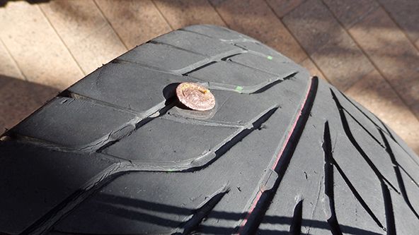 Having to quickly throw the spare on, i had that shameful feeling dawning upon me, as i stared at my bogan spec falcon. None the less, got me home where it had been patched up, so far no leaks. Really need to consider buying new tires, as they appear to be stale, judging by the ease of single pegging any how. Not too sure what to steer towards ( mind the pun ) as the front tires are budget " regatta ". The car for some time now has had the issue of tramlining, quite unnerving on country roads with volatile camber.  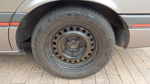 In regards to the cluster, the MDF board has been painted, as of now it looks far tidier. Will update with some pics and a video ( The speedometer is out by a long shot, need to get the VID reprogrammed )
_________________ Rolling around with a Barra 182 - equipped 1988 EA falcon |
|||
| Top | |
|||
| shooter |
|
||
|
Excuse the dumb question but what is the VID? Like you mean reprogram the pcm
|
||
| Top | |
||
| GrannyFalcon82 |
|
|||
|
Taken from manual
" The PCMs contain a memory area called a vehicle identification (VID) block. The VID block is used to store powertrain configuration information. The PCM VID block contains the factory settings for the configurable modules unless the PCM is flashed with a new calibration in which case some PCM parameters may be modified. " What I'm after is the Tire size, axle ratio and option index. In HP tuners i can adjust the vss pulses per mile, along with diff ratio and tire size to optimize the speed reading ( If it's off by something around 30kmh, it'll cause jerking, power surging etc.. ). However, seeing as the PCM came out of an automatic BA sedan, the PCM would be looking for signals from the ABS sensors via the CAN line, which i don't have. The PCM still seeks this vehicle speed sensor and i get a reading, but as far as i can understand it's not prioritized and I cannot adjust any vss settings as the VID is programmed for ABS only. However i can adjust " tire revolutions per mile ", i max out at 900, where the speed is still off by 20 - 30kmh. which would also refer to the VID as being ABS only. I'm hoping i can change the option index from " ABS Only " to " Other ", allowing me to adjust the vss settings in Hp tuners. I've tried one of Jaycars speedo corrector modules, not surprisingly did i suspect mine wouldn't work, I was right. Unless it's as simple as a resistor, it looks like it's a trip to ford so they can IDS up my pcm.
_________________ Rolling around with a Barra 182 - equipped 1988 EA falcon |
|||
| Top | |
|||
| GrannyFalcon82 |
|
|||
|
Picture of BA cluster in the falcon
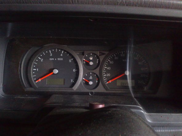 Sure it isn't absolutely perfect, but it's far more appealing than the EA sports series cluster. The fuel gauge appears to be pretty accurate, which I'm stoked with. Water temp doesn't seem to exceed 1/3 of the range on a daily basis. Rev count doesn't go backwards after 3000rpm ( yay ), however the speedo is far off, reading 110 - 120kmh whilst doing 80kmh, looks like a trip to fraud! Car seems a bit down on power, not sure if it's the skewed speedometer reading playing a major role. Time to change the plugs i dare say. What i found interesting was that the cluster was displaying a predicted gear selection based off of RPM vs Speed, in which case it appears that it's always one gear ahead ( eg. when in 3rd, cluster displays fourth. When in 2nd, cluster displays third. It can't quite grasp first gear however, quite funny to observe ) Once I'm able to adjust the vss settings, I'm hoping everything starts to smooth out a tad more. Here's a quick video : https://www.youtube.com/watch?v=aWmKU23 ... e=youtu.be
_________________ Rolling around with a Barra 182 - equipped 1988 EA falcon |
|||
| Top | |
|||
| johnnyeHCF |
|
|||
|
Hey Bayden, awsome stuff mate-good write up on the cluster-looks like it works pretty good-looks good too, been a bit slack of late (life getting in the way of the mod bug
_________________ XG DOHC-BARRA 182/Turbo kit/20% Underdrive and BA 4-SPEED + Tiptronic shifter |
|||
| Top | |
|||
| GrannyFalcon82 |
|
|||
|
Speedometer adjusting
For some time now I've been driving around with an out of wack speedo. Being a Barra, when the speedo is reading faster than it should be, there will be a little bit of overrun when decelerating ( Which can get extremely annoying ) Changing gears also becomes a lot rougher. Now, I was most certainly able to adjust the speed reading by only one parameter, " wheel revolution per mile ". However the software ( VCM editor ) Maxed out this parameter at 900, that was the limit, i could adjust no further. Therefore i was left to get on my knees and ring Fraud, at which point i was told there's not much that can be done for me, unless i had a Ute PCM to extract from. It would seem cheaper to buy a Ute PCM and be done with it, that's not quite the case. One would have to spend another $100 in credits to license said Ute PCM, the conclusion was drawn, both options were a rip off. 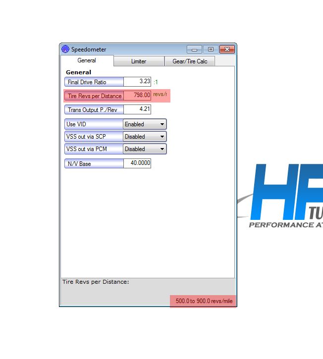 It dawned on me, there is actually a way i can solve both issues, for free! In theory, If i were able to change that parameter to a higher number, it would then lower the speed reading. Using an old, but gold program ( Cheat engine ) I was able to find the address of the maximum value for that parameter, and be able to edit it in 3rd party software. I Changed the max value for said parameter to 2000, giving me tweaking room. The sweet point seemed to be around 1150, however I'll need a GPS to confirm. The speedometer seems to stay pretty accurate through 0 - 100 range, although I'm still getting the slightest bit of overrun, I think I'm able to live with it. 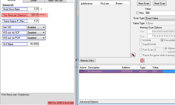 Why should one have to empty their pockets in order to solve a simple problem, that can actually end in a simple free solution. In other news, I had almost bid on a written off xr6T, someone won the bid for $800. I was extremely torn between doing so, and also thinking about the downtime, not to mention that xr6T had 250000 on the clock. Whether or not they were on the engine, I can't say. Could have gone down two ways, bought it and finding out the engine needs a rebuild and or turbo / damage. Or i simply could have just scored the best bargain there is. Eventually another sweet deal will come around the corner, hopefully with less Km's
_________________ Rolling around with a Barra 182 - equipped 1988 EA falcon |
|||
| Top | |
|||
| edfairmont4.0 |
|
|||
|
Great work with your conversion man
I actually used a ute ecu on my current conversion however not really relevent as I'm running the factory EL cluster. One question which I've never really looked into.... Your BA ecu is from a car with ABS right? Is that ECU without a VID block edit actually picking up speed from a standard EA Transducer and not going into limp home? Reason I ask is that I couldn't get around that problem in 09 when I did this conversion without that edit, Was BF ecu though... Didn't think that would be any different though. Thanks in advance
_________________ ED Fairmont, Ghia mock DOHC-T 11.6 @ 118 Trying to get back to the 1/4! |
|||
| Top | |
|||
| GrannyFalcon82 |
|
|||
|
edfairmont4.0 wrote: Great work with your conversion man I actually used a ute ecu on my current conversion however not really relevent as I'm running the factory EL cluster. One question which I've never really looked into.... Your BA ecu is from a car with ABS right? Is that ECU without a VID block edit actually picking up speed from a standard EA Transducer and not going into limp home? Reason I ask is that I couldn't get around that problem in 09 when I did this conversion without that edit, Was BF ecu though... Didn't think that would be any different though. Thanks in advance Indeed the BA ecu did pick up the factory vss signal, therefore it never went into limp mode. I'm guessing the BF range never had a Ute using a speed sensor in the gearbox extension housing like the BA range did. It does pick it up with a BA Sedan ( abs ) PCM, but without a VID block edit, there's only one parameter to edit in HP tuners ( And the max value of that parameter HAS to be forced higher, using a program such as cheat engine ) Too bad it's not as simple as hacking speed sensors into working with the can line, thus eliminating the issues with BF PCM's. Would make a fortune!
_________________ Rolling around with a Barra 182 - equipped 1988 EA falcon |
|||
| Top | |
|||
| GrannyFalcon82 |
|
|||
|
Garage has been really quiet as of late...
Anyhow I've decided to tinker around with HP tuners, seems I've gained some more torque on the low - mid end. With an under drive, extractors, 3.45 diff instead of a 2.92 and a tune It'd be pretty quick. Though with 3.45 gears I'd honestly consider an auto before I start snapping cables... Audio is crap, as are the rear tires which is the reason why I cannot launch it. https://www.youtube.com/watch?v=04z_eD6 ... e=youtu.be In short, All I've done is advance both forms of timing and removed various torque reductions, resulting in a power gain.
_________________ Rolling around with a Barra 182 - equipped 1988 EA falcon |
|||
| Top | |
|||
| Menicing |
|
||
Age: 37 Posts: 4 Joined: 13th Apr 2014 Ride: ED Fairmont, 88 XF Ute 351c Location: Brisbane |
Hey mate i'm currently doing a similar conversion but with fg n/a motor and pcm, just wondering if i could pm you and pick your brain
|
||
| Top | |
||
| Menicing |
|
||
Age: 37 Posts: 4 Joined: 13th Apr 2014 Ride: ED Fairmont, 88 XF Ute 351c Location: Brisbane |
Duplicate
Last edited by Menicing on Wed Jun 03, 2015 3:11 pm, edited 1 time in total. |
||
| Top | |
||
| Who is online |
|---|
Users browsing this forum: Google [Bot] and 10 guests |


