|
| DRHEMI |
|
|||
|
Just thought I would throw some pics of the ECU Dis-Assembled as the novice may not know how it comes apart
Here is a Linky for How to Install a J3 Chip by TI Performance {DESCRIPTION} but doesnt show the ECU apart Top with scews ready to be removed 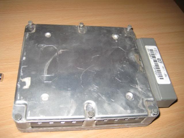 Top Cover Removed - you can see the 6 Screws that have been removed 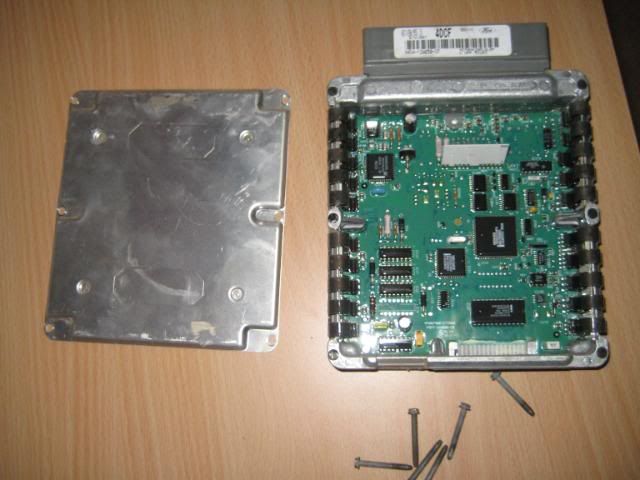 Bottom 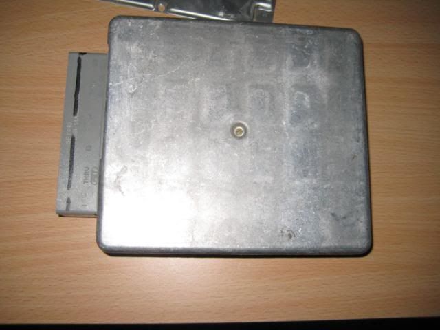 Bottom Cover Removed 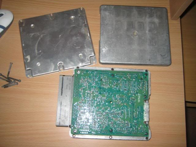 Dirty J3 Terminal 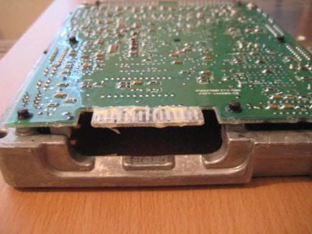 Dirty J3 Terminal Close Up 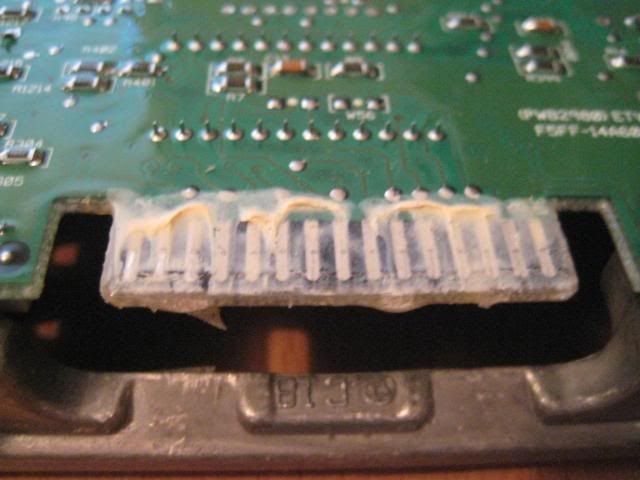 ] ]Other Side of Dirty j3 Terminal with a bit wiped off 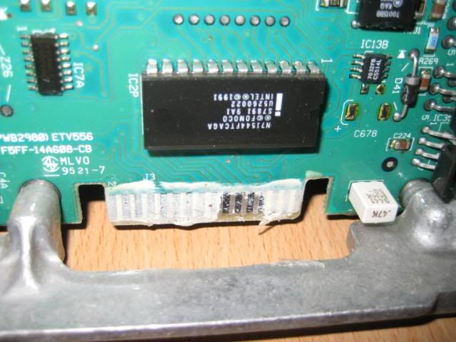 CLEAN J3 Terminal 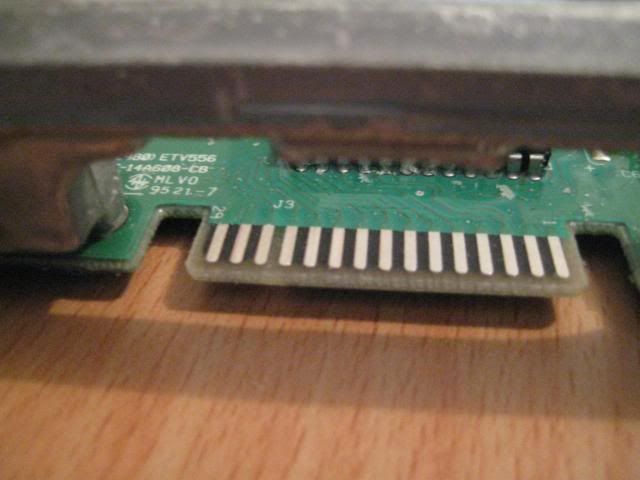 Other Side of CLEAN J3 Terminal 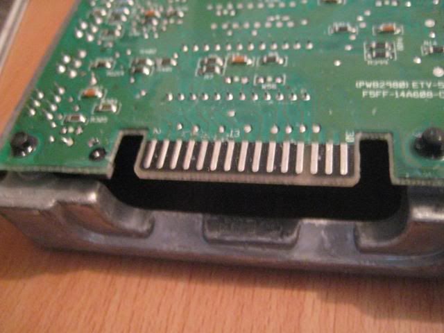
_________________ PROEF 13.46 @ 105.78mph - 1994 Ford Fairmont EF NA 6cyl Man 3.9 diff Sedan |
|||
| Top | |
|||
| galapogos01 |
|
|||
Posts: 1139 Joined: 27th Feb 2005 Ride: Supercharged EF Fairmont Location: T.I. Performance HQ |
Good pics! Got one of you scraping the lacquer off? It still manages to get a lot of people!
Jason
_________________ {DESCRIPTION} - {DESCRIPTION}, {DESCRIPTION}, {DESCRIPTION}, {DESCRIPTION} and more! |
|||
| Top | |
|||
| DRHEMI |
|
|||
|
Nah i didnt take one
The stuff you can see is the easy bit - but the clear laquer underneath is where you need metho and the screw driver You can see a lil bit of crap left over in one of the pics but that was cleaned up as good as the other side before re-fitting the J3 Chip to the new ECU
_________________ PROEF 13.46 @ 105.78mph - 1994 Ford Fairmont EF NA 6cyl Man 3.9 diff Sedan |
|||
| Top | |
|||
| rdiigen |
|
|||
|
Maybe a good tip to add would be to keep removing the lacquer until the connector stripes become copper in colour.
Because I was being really cautious, i removed some lacquer and the strips looked silver and shiny, So I 'thought' I was done. But the strips still felt a bit sticky (like when you feel the lacquer over the circuitboard itself), So i decided to just keep on scraping, throwing caution to the wind. I seriously thought i was starting to damage the strips because this stuff just kept on coming off and it still looked silver. I had another look at the PDF and was sure that the finished pic was copper looking. Finally i broke through and the copper started to show and I took a sigh of relief. Works great. |
|||
| Top | |
|||
| Who is online |
|---|
Users browsing this forum: No registered users and 0 guests |


