|
| nicco |
|
|||
|
Hi guys,
Getting my wiring diagrams together for the EMS install and I have a couple of questions. There are a few things on the standard EF ecu that I don't understand but strike me as possibly being important. I'm basically chasing a definition for each of the ones on this list, what it does and if I need it. Pin 10 - Compressor clutch enable Pin 30 - A/C evaporator air temperature Pin 41 - A/C clutch Pin 57 - Carbon canister purge Pin 69 - A/C Relay (WAC) Pin 86 - Blower fan speed Pin 91 - Signal return Pin 93 - Recirculation override (fresh/recirc) Pin 90 - Voltage reference +5v Is this the 5v supply to the rest of the car? The EMS has a 5v output, I'm assuming that's what I need to connect to there? Vehicle speed sensor Pin 58 - Vehicle speed sensor The EMS doesn't seem to need this, but just wondering if anyone can confirm or deny that for me. Also, there is four thermo fan relay outputs (pins 17, 42, 68, 48 for 1, 2, 3 and 4 respectively) Can I group some of these together, say 1 & 2 together and 3 & 4 together? I'm running low on the outputs from the EMS and need to consolidate a little bit. Also, EMS refers to the trigger and sync sensors for the timing. I'm assuming these are the crankshaft position sensor (pins 21 and 22) and cylinder identification [camshaft position] (pin 85) respectively? I realise these are some quite specific questions, but I'd appreciate any responses. These are all I need to get started. Thanks in advance, Nic |
|||
| Top | |
|||
| TROYMAN |
|
||
|
i can confirm the ems dont need a speed signal..
also the ems ignition trigger is the pip signal from the crank sensor and the ems sync is the cam angle sensor.. |
||
| Top | |
||
| nicco |
|
|||
|
Awesome, thanks Troy
|
|||
| Top | |
|||
| nicco |
|
|||
|
Actually, there is one more question, looking at the Ford wiring diagrams it seems as though the Idle speed controller operates by varying voltage between 8 and 11v. How do I simulate that with the EMS?
I've got on/off outputs, 4/5/6 wire stepper motor control or pulse width modulated outputs. From the EMS guff, it looks like I should be using a pulse width modulated output for the ISC? |
|||
| Top | |
|||
| TROYMAN |
|
||
|
yep they work quite well using pwm, the ems ecu's have a dedicated idle control as a digital output option, im running an au isc off my ems and it works good..
|
||
| Top | |
||
| tickford_6 |
|
||
Posts: 6449 Joined: 11th Nov 2004 |
What outputs are you using?
You can condense the thermo fan output down to two, OR we can operate them with out the ECU if need be. Cost will be two $40 temp switches. I'm about to do an EF fan conversion on my patrol. Have found two switches in the Tridon catalogue with has 3/8 BSP threads, sinlge terminal that pulls to ground with temp rise. One switches on at 87c and off at 82c the other is on at 95c and off at 90c. Those temps work well for my patrol. Low speed is the 87-82 switch high speed is the 95-90 switch. We can also add in a diode relay to switch on high speed with the A/C compressor clutch. Have a look here to see the full range and specs. http://www.tridon.com.au/Products/Produ ... 483&P=2014 I would like to know the conditions for carbon canister purge. If there is scope to have this working close to what ford designed it will be looked upon favourably (spelling?) by the engineer. The EMS doesn't need any of the A/C stuff. Pin 10 - Compressor clutch enable Pin 30 - A/C evaporator air temperature Pin 41 - A/C clutch Pin 69 - A/C Relay (WAC) Pin 86 - Blower fan speed Pin 93 - Recirculation override (fresh/recirc) But if you want you're A/C to work then you'll need a way of switching the clutch on and off with evap temp. <---- the EMS can't do this. You'll also need to turn the clutch OFF above 3500rpm. The stock ECU turns it off at full throttle, switching vs: RPM is better, as all you are trying to do is prevent over speed of the compressor. <--- the EMS can do this I think troyman has the rest covered. |
||
| Top | |
||
| nicco |
|
|||
|
Okay, thanks guys,
I'll condense the thermofans and just run them through the ECU, that'll work well. I realised I had C**k up with one other output, so I have a couple of spares now. Relays 1 & 2 together and 3 & 4 together? I've emailed EMS to ask about the aircon stuff, I'll post back if they give me a response. The only other thing that I need to know is the 5v and signal return pins on the EEC. Also Brad, looking through the wiring, it seems I will need something around a 24 or 25 pin connector. I can drop in tomorrow evening if you like. Cheers, Nic |
|||
| Top | |
|||
| tickford_6 |
|
||
Posts: 6449 Joined: 11th Nov 2004 |
{USERNAME} wrote: Okay, thanks guys, I'll condense the thermofans and just run them through the ECU, that'll work well. I realised I had C**k up with one other output, so I have a couple of spares now. Relays 1 & 2 together and 3 & 4 together? I've emailed EMS to ask about the aircon stuff, I'll post back if they give me a response. The only other thing that I need to know is the 5v and signal return pins on the EEC. Also Brad, looking through the wiring, it seems I will need something around a 24 or 25 pin connector. I can drop in tomorrow evening if you like. Cheers, Nic Yeah come around any time tomorrow. |
||
| Top | |
||
| TimmyA |
|
|||
|
I'd personally pull the EF fan gear out and throw it and fit EL control gear and fans... The EF has a single winding fan and a dual winding fan... Dual wound motors are twice as prone to issues...
The EL system is two states... Both fans low... or Both fans high... Your output brings on relay 1 and this gives you low... You second output brings on relays 2 and 3 and gives you high speed... The EF system is rather complicated and I did have a lend of the workshop manual last weekend to see how it worked and now I can't remember... I can however tell you it has three states... The following relays are on to get each state: Low/Low R2 & R4 High/Low R2 & R3 High/High R1 & R2 & R3 You could then achieve Low/low and high/high You'd have to put a diode between R2 & R4 so current flows from R4 -> R2 Hook your low speed trigger to R4 You'd have to join R1 & R3 and put a diode between them & R2 so current flows from R1+R3 -> R2 and hook your high speed trigger to R1+R2... This would achieve the combinations above... Or alternatively you could fit an EL relay block... hook the red/green coil supply to the red/green cold supply on the EL block... Hook the big yellow supply to EL big yellow supply... Then blue/white is your low speed trigger... And blue is your high speed trigger (both blue/white & blue must be powered to get high speed)... Hope that makes sense? Though I may have confused the hell out of you... As even I'm feeling a tad lost... Cheers, Tim
_________________ {DESCRIPTION} |
|||
| Top | |
|||
| tickford_6 |
|
||
Posts: 6449 Joined: 11th Nov 2004 |
{USERNAME} wrote: I'd personally pull the EF fan gear out and throw it and fit EL control gear and fans... The EF has a single winding fan and a dual winding fan... Dual wound motors are twice as prone to issues... The EL system is two states... Both fans low... or Both fans high... Your output brings on relay 1 and this gives you low... You second output brings on relays 2 and 3 and gives you high speed... The EF system is rather complicated and I did have a lend of the workshop manual last weekend to see how it worked and now I can't remember... I can however tell you it has three states... The following relays are on to get each state: Low/Low R2 & R4 High/Low R2 & R3 High/High R1 & R2 & R3 You could then achieve Low/low and high/high You'd have to put a diode between R2 & R4 so current flows from R4 -> R2 Hook your low speed trigger to R4 You'd have to join R1 & R3 and put a diode between them & R2 so current flows from R1+R3 -> R2 and hook your high speed trigger to R1+R2... This would achieve the combinations above... Or alternatively you could fit an EL relay block... hook the red/green coil supply to the red/green cold supply on the EL block... Hook the big yellow supply to EL big yellow supply... Then blue/white is your low speed trigger... And blue is your high speed trigger (both blue/white & blue must be powered to get high speed)... Hope that makes sense? Though I may have confused the hell out of you... As even I'm feeling a tad lost... Cheers, Tim The EF fans are so simple to wire as low-low and high-high. It can be done with 2 relays and no nothing more. Done it many times before when doing retrofits to other cars. When I do my Patrol It will use Tridon TFS110 as the low temp (low-low) switch and TFS as the high temp (high-high) switch. It will also have two manual overrides to either bring on high speed in an effort to pre-empt temp rise when trying to pull 4 tonne up mountain ranges OR to turn everything off for deep water crossing. Will also bring on high-high with the A/C clutch It will be simple to use two outputs from the EMS to run two relays to give low-low and high-high. |
||
| Top | |
||
| TimmyA |
|
|||
|
cool cool...
So does this involve re-wiring of the fan control? You can't use what is there from factory? I just feel Ford went way overcomplicated with EF thermofans... EL ones make heaps more sense... And then they stuck with this design through to the last two fan models... Sure FG's are single fan now? Cheers, Tim
_________________ {DESCRIPTION} |
|||
| Top | |
|||
| tickford_6 |
|
||
Posts: 6449 Joined: 11th Nov 2004 |
{USERNAME} wrote: cool cool... So does this involve re-wiring of the fan control? You can't use what is there from factory? I just feel Ford went way overcomplicated with EF thermofans... EL ones make heaps more sense... And then they stuck with this design through to the last two fan models... Sure FG's are single fan now? Cheers, Tim Very minor changes to the factory wiring. |
||
| Top | |
||
| nicco |
|
|||
|
Awesome discussion here guys, thanks.
I found this in the workshop manual, confirms what you had said Timmy: 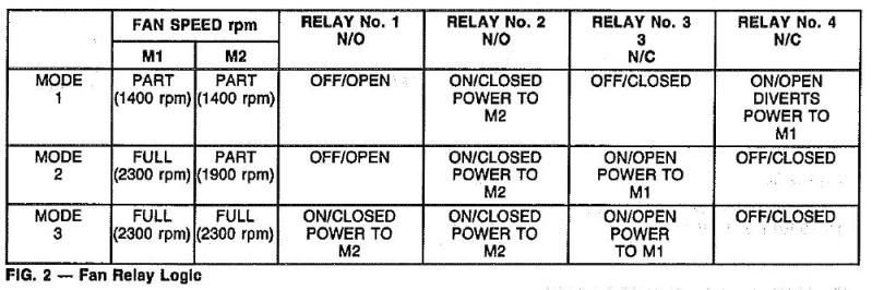 So basically, I can control two fan speed (modes 2 and 3) with two outputs - relays 2 &3 together and relay 1 separate. Also means no mods to the factory wiring (I hate wiring Just gotta work out this 5v and signal return now and then sorted. I get the impression just thinking about it logically that it is a 5v supply to the sensors in the car, and the signal return needs to go to ground... hrmmm... Brad, I'll drop around this arvo and grab that plug off you. Cheers, Nic |
|||
| Top | |
|||
| TROYMAN |
|
||
|
{USERNAME} wrote: Awesome discussion here guys, thanks. I found this in the workshop manual, confirms what you had said Timmy: So basically, I can control two fan speed (modes 2 and 3) with two outputs - relays 2 &3 together and relay 1 separate. Also means no mods to the factory wiring (I hate wiring Just gotta work out this 5v and signal return now and then sorted. I get the impression just thinking about it logically that it is a 5v supply to the sensors in the car, and the signal return needs to go to ground... hrmmm... Cheers, Nic i would use mode 1 and mode 3 on the fans, that way at low temps the fans are on low speed, and when the temp gets mid to high the fans will switch to high.. although mine are very simple, both fans come on full at 94deg and switch of at 89deg. they only stay on for 30 second at a time and while moving at 60km or more the temp stays just low enough not to need the fans.. the 5v is power to the sensors there is a signal return and the sensor signal earth.. are you running the ems as a piggyback or stand alone???? |
||
| Top | |
||
| nicco |
|
|||
|
The benefit of running modes two and three, in my eyes, is that I can halve the number of outputs the ECU needs. If it's temperature dependent there shouldnt be an issue with either speed... I think...
Yeah, I was planning on running the EMS stand alone. Although the a/c issues combined with the thermofan thing are making me think seriously about leaving the stock ecu in to control them. Thanks about the 5v too. |
|||
| Top | |
|||
| Who is online |
|---|
Users browsing this forum: No registered users and 0 guests |
