|
| dylanfh |
|
||
|
Thanks,so just to clear things up,2 wires go to 1 end of the 3 joined resistors and 1 goes to the other end?.So this will kind of make it like a 2 stage setup?.It will be going into a 5.0 EF Ghia in about 2 days.If ive got the wiring idea of it ill let everyone know how it goes.
|
||
| Top | |
||
| 93_eb_fairmont |
|
|||
|
No it isnt a 2 stage setup, in order for a resistor to resist, electricity has to enter one end and exit the other. What you are going is going to be an on/off setup. If I were you I wouldnt put the LED in either, just to keep it simple and easy to mount so its just 1 switch and 3 wires. Conduit works well for stuffing the resistors into and then just tape it all up.
Yes, one wire on one end of the joined resisotres, 2 on the other. While youre at jaycar ask him if he's got any adjustable pots to do the same job itll be a lot simpler to wire but a bit more expensive but hen youll have a pot
_________________ How many bears could Bear Grylls grill if Bear Grylls could grill bears? |
|||
| Top | |
|||
| dylanfh |
|
||
|
Sorry for all the questions,dont want to stuff it up.
can i use as in both these diagrams or only 1 (top or bottom diagram?.). Ive tidied up the pic a bit better than before. 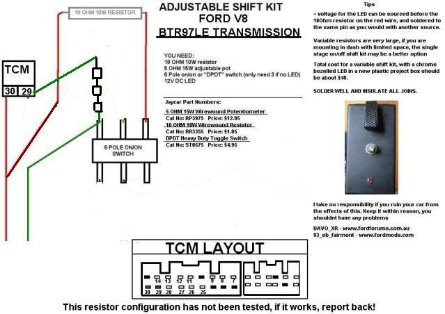 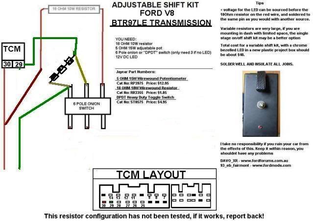
|
||
| Top | |
||
| slywog |
|
||
|
have you sorted the wiring out for the au v8 trans shift kit yet ????? if so whats the numbers ?
|
||
| Top | |
||
| ed5speeddanny |
|
||
|
Tried it today without switch kept going into limp home if resistance value was higher in pin 30 than the resistance in 29. Now just going to try having 25 ohm in 29 and 18 ohm in 30.
|
||
| Top | |
||
| FordFairmont |
|
||
Posts: 6113 Joined: 8th May 2007 |
{USERNAME} wrote: have you sorted the wiring out for the au v8 trans shift kit yet ????? if so whats the numbers ? same as EF-AU 6 cylinder |
||
| Top | |
||
| Ghiaed1994 |
|
|||
|
{USERNAME} wrote: Well, here it is: Im sure those pin numbers are correct but only 99% that the resistor values are right, someone should try it to confirm! I'll get around to doing a tech doco with all of them now.  Hopefully that is high enough res. Think the BTR 97LE goes from EB to AU3 anyway so should be able to work on all of them. Can we please have the original diagram reposted as it appears to have been removed or expired. Really interested in this, thanks. Nathan
_________________ 1994 ED Fairmont Ghia |
|||
| Top | |
|||
| wtbdlltd |
|
||
|
{USERNAME} wrote: {USERNAME} wrote: Well, here it is: Im sure those pin numbers are correct but only 99% that the resistor values are right, someone should try it to confirm! I'll get around to doing a tech doco with all of them now. Hopefully that is high enough res. Think the BTR 97LE goes from EB to AU3 anyway so should be able to work on all of them. Can we please have the original diagram reposted as it appears to have been removed or expired. Really interested in this, thanks. Nathan YES PLEASE |
||
| Top | |
||
| Who is online |
|---|
Users browsing this forum: No registered users and 0 guests |

