|
| 93_eb_fairmont |
|
|||
|
Well, here it is:
Im sure those pin numbers are correct but only 99% that the resistor values are right, someone should try it to confirm! I'll get around to doing a tech doco with all of them now.  Hopefully that is high enough res. Think the BTR 97LE goes from EB to AU3 anyway so should be able to work on all of them.
_________________ How many bears could Bear Grylls grill if Bear Grylls could grill bears? |
|||
| Top | |
|||
| banarcus |
|
|||
|
AU V8s had the automatic control integrated with the ECU like that of the 6cyl.
|
|||
| Top | |
|||
| 93_eb_fairmont |
|
|||
|
{USERNAME} wrote: AU V8s had the automatic control integrated with the ECU like that of the 6cyl. Well that info's for the TCM operated gearboxes.
_________________ How many bears could Bear Grylls grill if Bear Grylls could grill bears? |
|||
| Top | |
|||
| wrexed03 |
|
||
|
I just tried this on my NL 5.0 Either i did something wrong or it doesnt work.
Im assuming the +V -V wires are not mandatory. They just power the led? Can we verify its pins 29 & 30 please. Photos of the TCU end would be great if anyone has done this. Anyone else tried it? Regards |
||
| Top | |
||
| 93_eb_fairmont |
|
|||
|
Yeah I havent tried it, if thats not working then I dunno what it is. + and - are for LED only. That was a link I was sent for the TCM wiring.
_________________ How many bears could Bear Grylls grill if Bear Grylls could grill bears? |
|||
| Top | |
|||
| 93_eb_fairmont |
|
|||
|
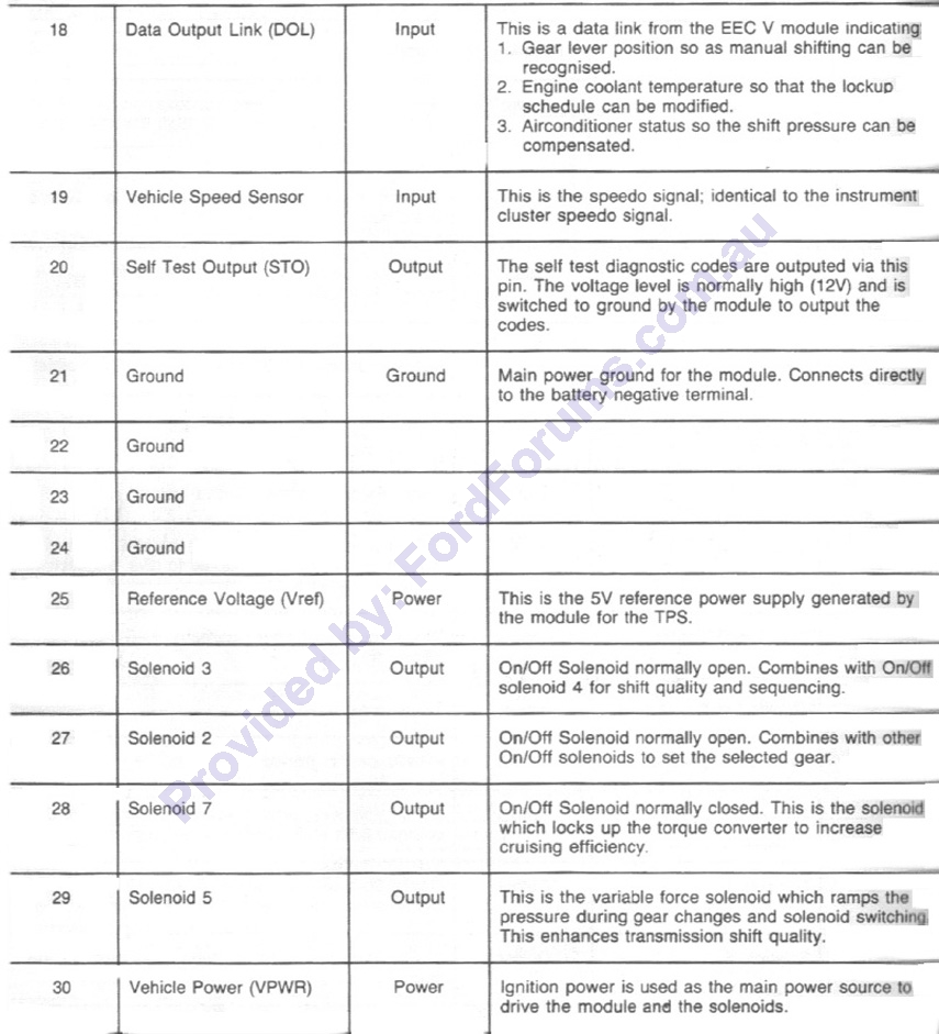 definately pin 29 and 30
_________________ How many bears could Bear Grylls grill if Bear Grylls could grill bears? |
|||
| Top | |
|||
| wrexed03 |
|
||
|
I will have another crack at it in the morning. Having the +V and the -V attached managed to take out a 30amp fuse on the assesories side. Will try it without these two and leave the rest. Will post back with my results.
Regards |
||
| Top | |
||
| 93_eb_fairmont |
|
|||
|
Yeah well make sure the switch youre using the sides arent in contact with eachother at all. I reckon if its not working its something to do with the resistor values.
_________________ How many bears could Bear Grylls grill if Bear Grylls could grill bears? |
|||
| Top | |
|||
| 93_eb_fairmont |
|
|||
|
{USERNAME} wrote: I will have another crack at it in the morning. Having the +V and the -V attached managed to take out a 30amp fuse on the assesories side. Will try it without these two and leave the rest. Will post back with my results. Regards You didnt hook - up to the switch did you? Short of dodgy wiring or the wrong sort of switch I cant see how a fuse would blow?
_________________ How many bears could Bear Grylls grill if Bear Grylls could grill bears? |
|||
| Top | |
|||
| wrexed03 |
|
||
|
Parts are exactly whats specified in the diagram. I checked and rechecked everything. It's pretty straight forward according to the diagram. Will suss it out one more time and see.
Regards |
||
| Top | |
||
| 93_eb_fairmont |
|
|||
|
If you have a multimetre just check and make sure either coloums of the switch arent touching. each side should not touch.
_________________ How many bears could Bear Grylls grill if Bear Grylls could grill bears? |
|||
| Top | |
|||
| wrexed03 |
|
||
|
When you refer to colums im assuming your refering to the terminals on the switch.
|
||
| Top | |
||
| 93_eb_fairmont |
|
|||
|
Yeah the 2 sides and the 3 pins on each side, the 3 pins going down, 2 will touch whichever position its in, but each coloumn of 2 pins should not touch the other
_________________ How many bears could Bear Grylls grill if Bear Grylls could grill bears? |
|||
| Top | |
|||
| wrexed03 |
|
||
|
Just looking at the diagram.
Looking at the switch the first 2 pins top row go through the adjustable potentiometer and to the green wire so you cut pin 29 wires and splice these two in between. (When switch in this position) Then you have the middle pin and the 3rd pin which go through the resistor red wire. Which attaches to pin 30 wire (When switch in this position) So there is no need to use the bottom 3 pins at all. I will recheck with the multimeter the switch to make sure its functioning correctly. |
||
| Top | |
||
| 93_eb_fairmont |
|
|||
|
{USERNAME} wrote: Just looking at the diagram. Looking at the switch the first 2 pins top row go through the adjustable potentiometer and to the green wire so you cut pin 29 wires and splice these two in between. (When switch in this position) Then you have the middle pin and the 3rd pin which go through the resistor red wire. Which attaches to pin 30 wire (When switch in this position) So there is no need to use the bottom 3 pins at all. I will recheck with the multimeter the switch to make sure its functioning correctly. Correct, only if you want an LED do you need the 6 pole switch.
_________________ How many bears could Bear Grylls grill if Bear Grylls could grill bears? |
|||
| Top | |
|||
| Who is online |
|---|
Users browsing this forum: No registered users and 0 guests |
