|
| bradders |
|
|||
|
{USERNAME} wrote: PID closed loop idle control with the MS2/e code works well, but it takes some time to get it tweaked right. I didnt get any pm from you though When it comes to tuning PID theres a couple of approaches. The first thing you can do is characterise the process, might be a little difficult, but if you can relate the process variable (idle) directly to the manipulated variable (PWM output) with a step change; you can come up with whats called a transfer function. From that theres two major approaches to tuning. My preffered approach is specifying a reference trajectory transfer function, possibly including a first order "filter" (to keep the denominator a higher order than the numerator). With algebraic manipulation of the transfer function with reference trajectory you essentially get the PID values to give you perfect control. A quicker simpler approach is set ti and td to zero (or ti=1000000 if reset rate), and keep increasing the gain on the closed loop (proportional only controller) once you've found the verge of instability (very slightly growing oscillations) you can use the following tuning rules: Code: Controller type kc ti td P 0.5kcu PI 0.45kcu pu/1.2 PID 0.6kcu pu/2 pu/8 Ziegler, J. G. and N. B. Nichols, "optimum settings for automatics controllers," trans. ASME, 64, 759 (1942) Kcu is the gain of the controller at which it begins to become unstable, and pu is the period between oscillations. Its usually best to measure say ten oscillations then divide the overall time by the number of oscillations. Once you'd used Z-N you should find there is reasonable control, but it is an approximate method so some tweaking will be required after.
_________________ PH 4480 racing extractors
|
|||
| Top | |
|||
| ToranaGuy |
|
|||
|
{USERNAME} wrote: Yeah I'll be keeping the remote locking part of smartlock yeah I can't decide weather to rip apart the ECU's I have or get a dead one Cool. Standard auto ecu's are pretty cheap & easy to come by, so if you have a couple, just rip one open & use it. I have recently found out my mighty boy doesn't need to meet ANY emissions standards, so my turbo & EFI with MegaSuirt is going to be going ahead running petrol. Which will be much easier than the LPG setup i was looking at running with the MegaSquirt. Cheers ToranaGuy
_________________ I am the ToranaGuy!|74 Lh Torana Turbo|78 Hz PanelVan|86 Mighty Boy Ute|93 EB2 Ghia,GT Mockup,5spd,LPGI,Full Leather|2 x EB Xr8 5spd's|{DESCRIPTION}|{DESCRIPTION}|{DESCRIPTION}| |
|||
| Top | |
|||
| bradders |
|
|||
|
I just realised today that the bloody missing tooth sensor is variable reluctance! i had assumed ford would have just used hall effect, so i've built my MSII to work off hall effect. Now theres two ways i can go about this.
1, modify the jumpers on the board to allow the MSII to work with variable reluctance, but then that means i'll have to disconnect the sensor from the stock ECU completly, since the stock ECU seems to add a bias to the signal? 2, retrofit a hall effect sensor, but if i keep the stock VR in place (because i'm going to allow the stock ecu to control the dash and fuel pump) the sensor will be off TDC. I've got a couple of other questions as well, is the first tooth after the missing tooth TDC, or is the missing tooth TDC? now i don't think its essential because its waste spark, but the cam sensor is VR too? so if i'm using the MSII-E how do i wire in that signal? the only reason i want it is so that the 1st bank of injectors fire for 1,5,3 before they spark, then the 2nd bank before 6,2,4, if i don't have the cam signal then the banks might fire in the correct order one time then the incorrect order the next, so my understanding is that half of the time i'd have a smooth idle and the other half a rough idle. thanks guys progress report, well i've followed the MSII-e modifications, and now have three coil drivers built into the MSII (i'll include some pictures later) for the additional grounds i soldered directly onto the legs of R38 and R37 and used a bit of heat shrink. I also fitted the TIP120 transitor to drive the idle controller, the three extra transitors have been mounted to the case above the heatsink strip. in order to provide a reasonable ground, i've used two pins off the db37 connector for each coil driver output, i used the spr4 and ign pins for the onboard coil driver, IAC1A+B for the second, and IAC2A+B for the third coil driver. I also used the prototyping area to attach the new resistors.
_________________ PH 4480 racing extractors
|
|||
| Top | |
|||
| ToranaGuy |
|
|||
|
Nice work, would love to see the pics.
Cheers ToranaGuy
_________________ I am the ToranaGuy!|74 Lh Torana Turbo|78 Hz PanelVan|86 Mighty Boy Ute|93 EB2 Ghia,GT Mockup,5spd,LPGI,Full Leather|2 x EB Xr8 5spd's|{DESCRIPTION}|{DESCRIPTION}|{DESCRIPTION}| |
|||
| Top | |
|||
| 66 coupe |
|
||
|
you can piggyback the stock VR sensor brown wire, but you need to connect the stock VR - (grey wire) to the MSII gnd also. It will work. Generally set you MSII pots full CCW, then 1 turn CW on each.
Tooth 1 angle is 60* btdc, therefore the missing tooth is 70*. This is how the ecu's determine the ign timing - if tooth 1 was TDC then it could only predict the timing, not calculate it. Dont worry too much about the injector banks and sequencing causing it not to idle, just set it up with the two banks, 1-2-3 and 4-5-6, 2 squirts simultaneous. You dont need to use the sync sensor, but you can connect it if you want to set up semi-seqential or sequential injection at a later stage (MS3). You need to build a second VR interface for the sync sensor, using an LM1815 is the best way to go. for the PWM valve, a TIP120 will work, but your much better off using an IGBT for it (same as coil driver) also a 1N4004 diode from the - side of the PWM valve and band side to +12v ign to reduce flyback effects. the PWM settings are a bit tricky to get right, but persevere with it, and you will get good results. |
||
| Top | |
||
| ToranaGuy |
|
|||
|
Very informative post 66coupe, and it will help me a lot personally as well, as i'm setting up a MS to run on a Triumph 2600 that was originally a mechanical injection setup, using a lot of borrowed E series parts like the TB & so on, as i've wrecked a couple & hard parts aplenty lol.
Cheers ToranaGuy
_________________ I am the ToranaGuy!|74 Lh Torana Turbo|78 Hz PanelVan|86 Mighty Boy Ute|93 EB2 Ghia,GT Mockup,5spd,LPGI,Full Leather|2 x EB Xr8 5spd's|{DESCRIPTION}|{DESCRIPTION}|{DESCRIPTION}| |
|||
| Top | |
|||
| bradders |
|
|||
|
lol i was just about to thank 66 as well, very useful information. How'd you get to know so much 66? It makes things so much easier when someone else can shed some light on the situation. I was a bit uncertain about which wire was which (brown/grey) since they both had like 2.6V DC, i think the brown one varied by like 1v AC (i don't have an oscilloscope although i sorta built one i hadn't used it, just used a multimeter)
So will the ECU still work if i ground out the grey wire onto the MSII? do i still leave the grey wire connected to the stock ECU? i'm going by the diagram that i found on another fordmods posting, it only showed the brown and grey wire going to the crank sensor (didn't tell me it was VR, but i should have realised since there was only two wires!) i just want to keep the stock ecu on standby just in case if you know what i mean. furthermore, would you say there is much benefit to implimenting the MSII on the AU? (its a series one non tickford but i put in a tickford engine) since the EEC-V has sequential injection and knock detection. My thinking is that the EEC-V is built to be generic but each engine is different, so an ECU that can be tuned to a specific car should be better even if it doesn't (currently) have knock detection. i don't suppose you have an MSII-E .msq file to get me started for the AU? even if its a file for dizzy or whatever at least the crank timing and fuel injection would give me a good start. Thankyou everyone whos replying and helping me out, its good to know theres people out there who know what their doing and can guide me in the right direction.
_________________ PH 4480 racing extractors
|
|||
| Top | |
|||
| 66 coupe |
|
||
|
pm me your email address
|
||
| Top | |
||
| bradders |
|
|||
|
why do you recommend the IGBT? faster switching times, greater effeciency? i had figured that any switching lag on the transistor would have been negligible compared to the PWM frequency (although i don't know what the pwm freq is, nor the transistor switching time) if switching times is the issue i'm sure my tuning methodology will be able to cope.
_________________ PH 4480 racing extractors
|
|||
| Top | |
|||
| 66 coupe |
|
||
|
I have found the Tip120 can run quite hot switching the ford PWM valve, so your better off using an IGBT for overall reliability, Plus the fact the IGBT is designed to switch inductive loads, and can habdle the flyback.
Its up to you what you use, for overall reliablility i use an IGBT |
||
| Top | |
||
| bradders |
|
|||
|
i'll swap it over then since i have to open it up, i can leave the base resistor the same, just swap over the one component?
_________________ PH 4480 racing extractors
|
|||
| Top | |
|||
| bradders |
|
|||
|
{USERNAME} wrote: you can piggyback the stock VR sensor brown wire, but you need to connect the stock VR - (grey wire) to the MSII gnd also. It will work. Generally set you MSII pots full CCW, then 1 turn CW on each. so i can tap the signal off the brown wire, do i tap the grey wire as well, or do i disconnect it from the stock ECU completely?  Will the stock ECU continue to work if the grey wire is brought to MSII ground and pin or brought to MSII ground and disconnected?  alternativly, i was reading this: http://www.megamanual.com/ms2/vradjust.htm i could just raise the trigger threshold resistor (R56) to around the bias offset i measured at the brown wire before and leave the hysterisis resistor (R52) to ~1 turn. (option C) 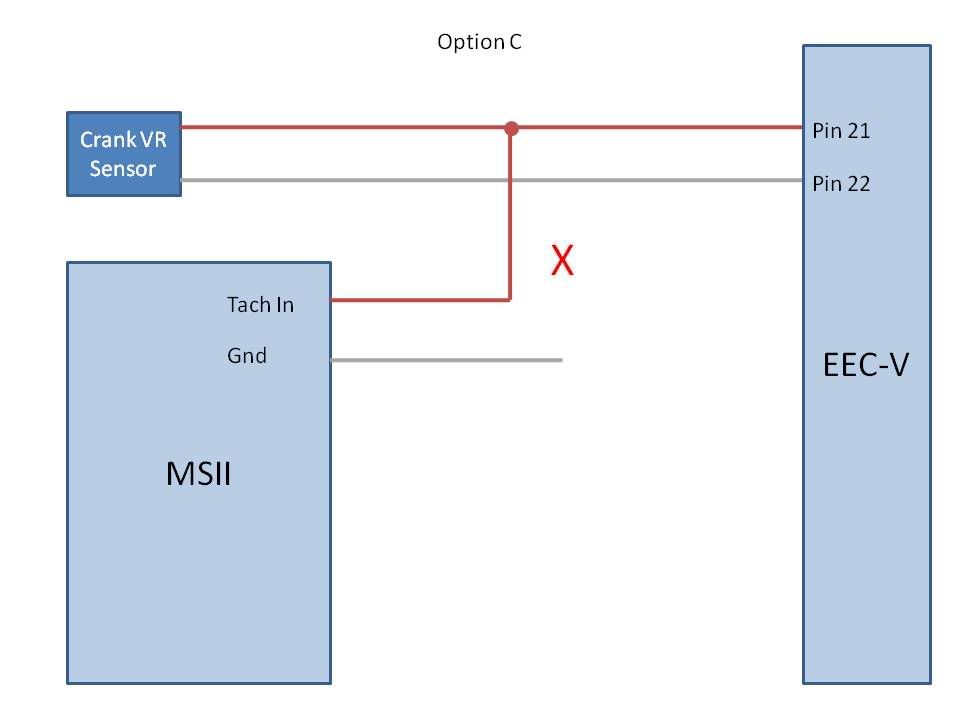 heres some pictures 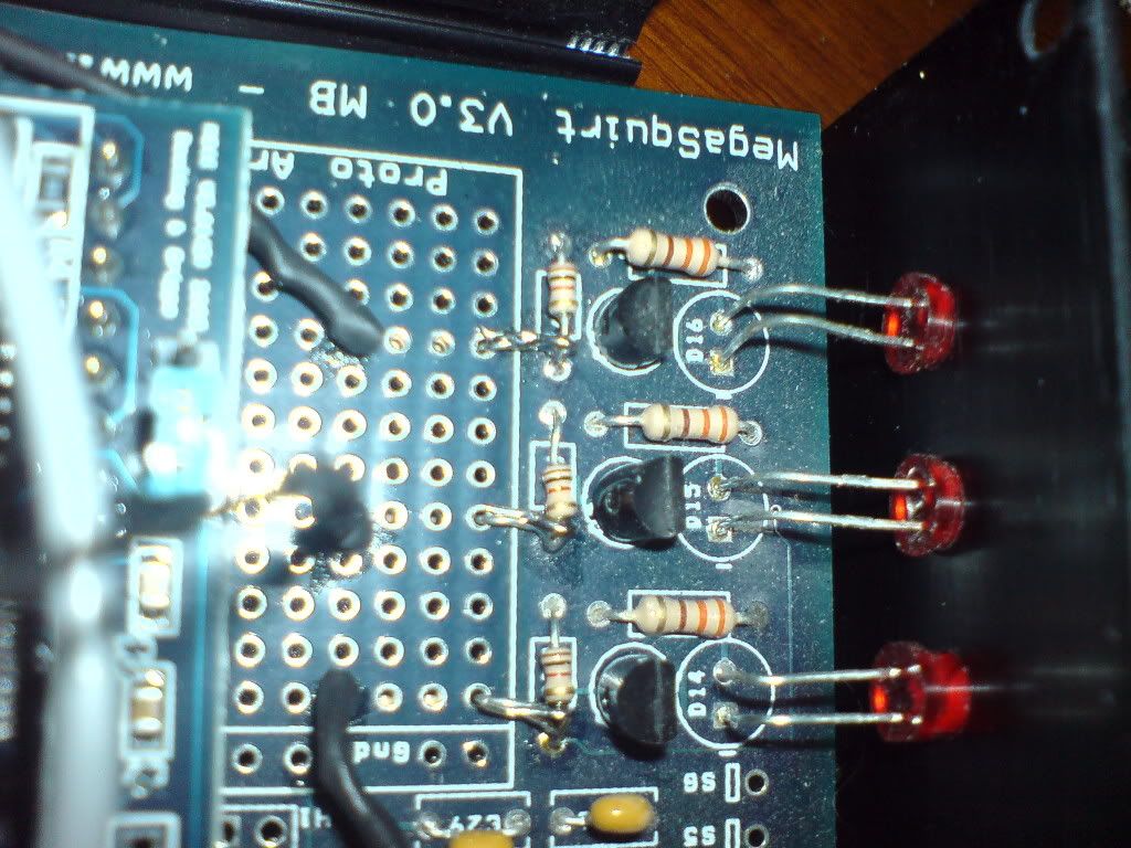 here you can see the signal wires used to control the coil drivers (black heatshrink) and where the driver resistors have been tapped off the existing resistors 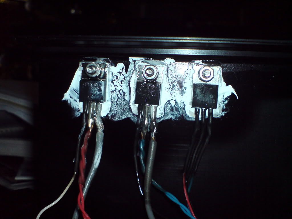 Here are the additional transistors used to ignite the coils and drive the pwm controller along with heatsink paste all over the place  self explanatory 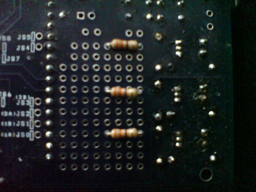 these are the additional resistors required to deliver the signal current to the new transistors 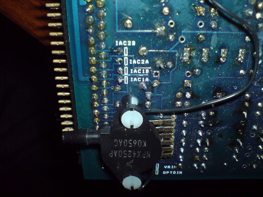 IGN jumpered to IGBTOUT jumpered to SPR4 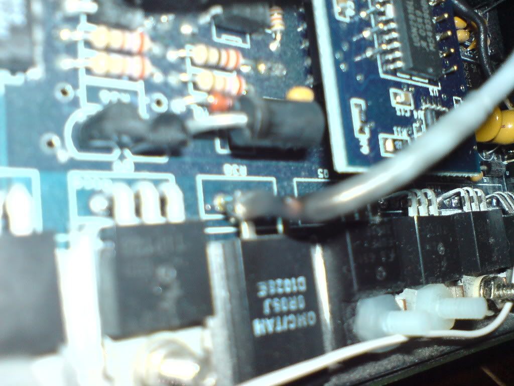 connect to the meaty grounds of R37 and R38, using fairly meaty cable and heatshrink to make the connection 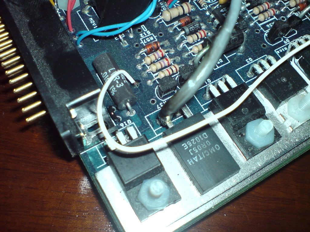 connect to the meaty grounds of R37 and R38, using fairly meaty cable and heatshrink to make the connection 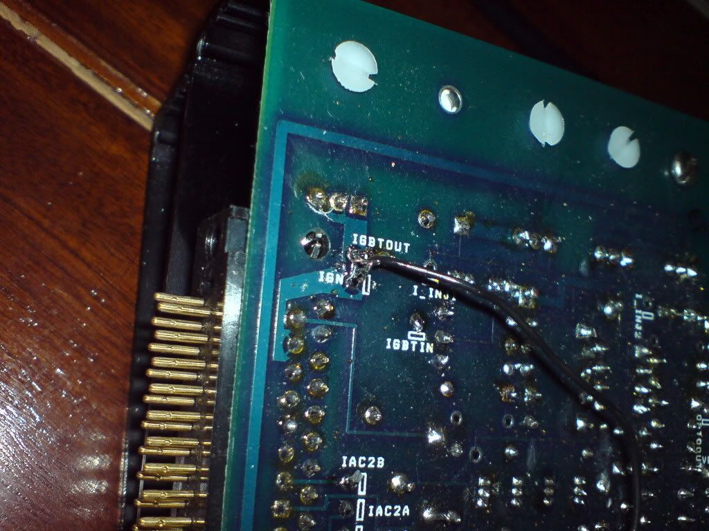 IGN jumpered to IGBTOUT jumpered to SPR5 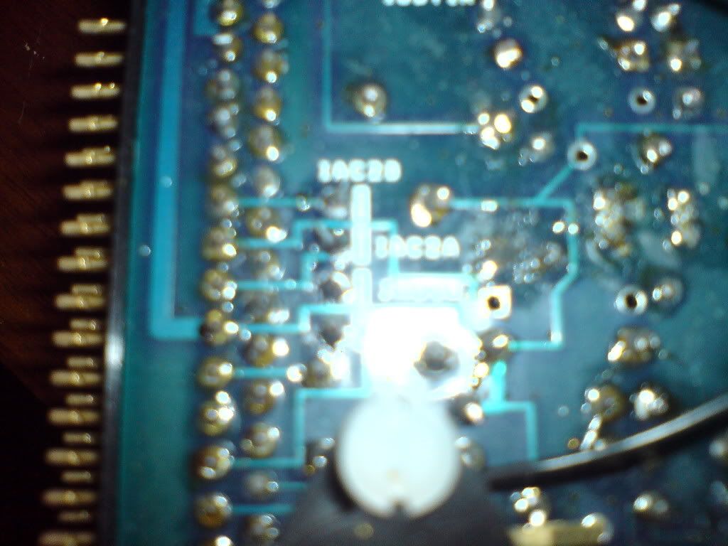 coil B is connected to IAC1A and IAC1B output on R37 connector, coil C is connected to IAC2A and IAC2B. Using two spare pins allows for the sinking of the current 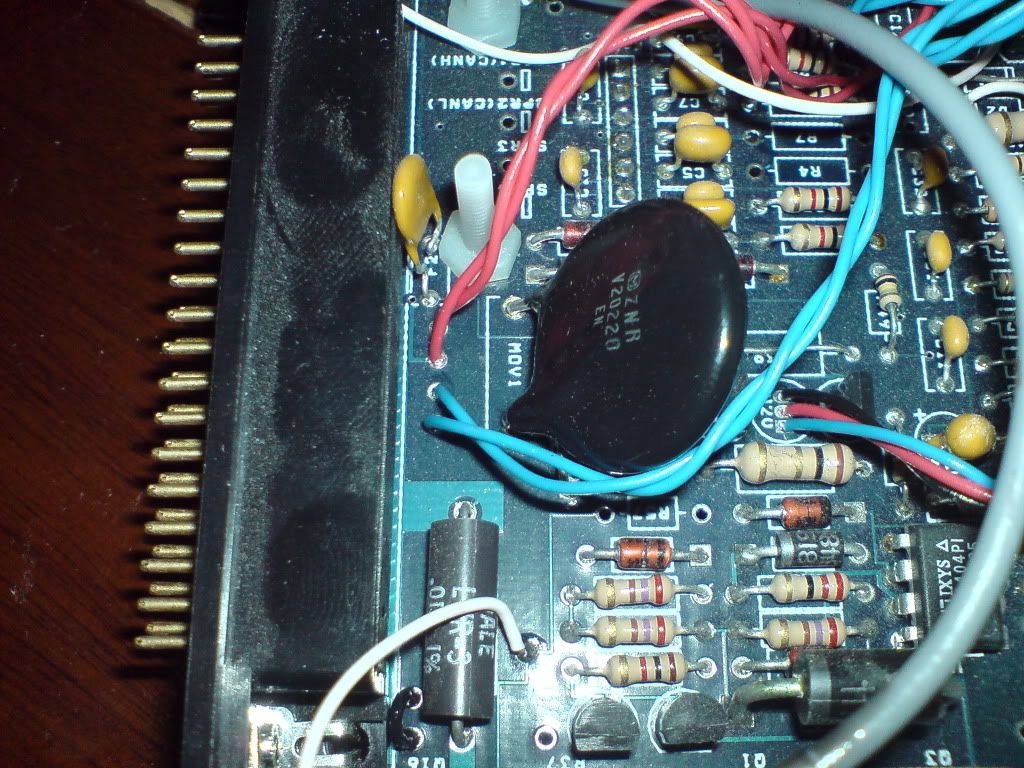 here you can see the coil driver signal for coil A (white wire) connected to IGBTIN, and the output wires for coil B and C, two wires were used to better handle the current
_________________ PH 4480 racing extractors
|
|||
| Top | |
|||
| bradders |
|
|||
|
great success, i wired all my sensors in today after switching to the VR circuit. Using wiring option C. It worked first time to my amazement! once it was in i stopped the engine, opened it up and measured the voltage on R48 and R54 to make them the same by adjusting R56, then i set the hystersis to 1 turn as 66 coupe suggested. i found that it started sparking sooner (can tell from the LED's indicating spark) after starting the engine.
_________________ PH 4480 racing extractors
|
|||
| Top | |
|||
| 66 coupe |
|
||
|
use 'A' as you will get sync losses without the ground connected to the VR. The VR needs to be referenced to ground with the megasquirt.
|
||
| Top | |
||
| bradders |
|
|||
|
more progress updates, this morning i had the MSII in the car reading all the sensors, but i kept loosing serial link. turns out there was a tiny tiny solder bridge on the daughter card, that took a little while to identify, additionally, the MSII had been drawing alot of current and the voltage at the regulator was 3v i guessed that maybe i'd put the wrong protection zener in, but it turns out i had put the 5.6v zener in but it wasn't working properly (confirmed because it was hot), so i removed the zener (D19) the voltage was fine.
_________________ PH 4480 racing extractors
|
|||
| Top | |
|||
| Who is online |
|---|
Users browsing this forum: No registered users and 0 guests |

