|
| sly |
|
||
|
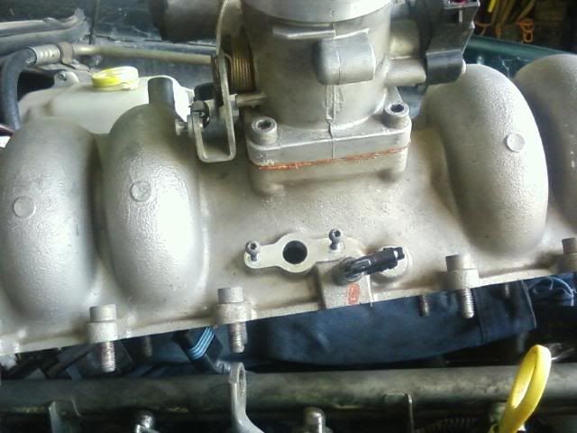
This is the underside of the top half of an AU1 BBM. The hole dead-centre of the photo is where the TMAP sensor mounts. It's held in place, obviously, by the 2 screws either side of the hole. Not an easy place to get to, being tucked up under the throttle body when the BBM is bolted on.
 This is the AU1 wiring plug, which like the sensor, is unique to the AU1. That is, it is not only different to the AU2 and later, it also is different to the E-series. 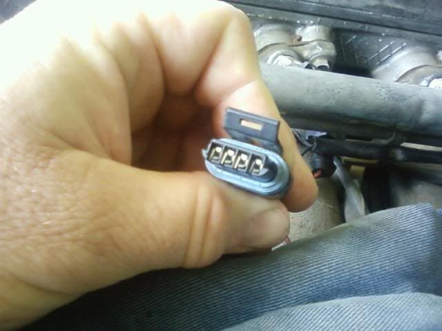 The same AU1 plug viewed from the other end, showing the wiring colours. The detail is a bit blurred, but you should be able to make out the pin-position labelling A B C and D directly above the wires. The "official" wiring colours as per the Ellery's and Gregory's manuals are, from left to right, Black/White, Black/Yellow, Orange/Black and Blue/Yellow. Tough luck if you have the Haynes AU1 manual, it has the wrong colours on the wiring diagram... along with heaps of other errors. 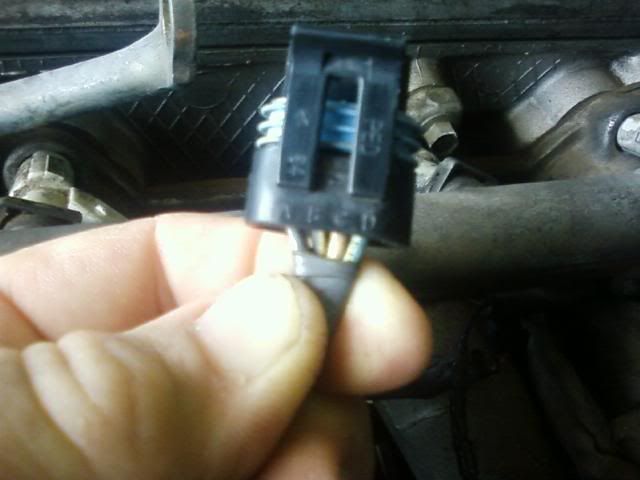 The sensor itself, from the manifold side... 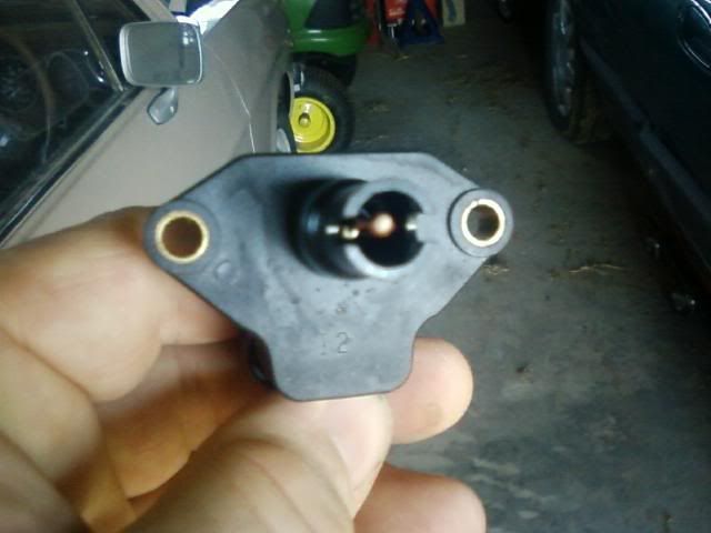 ...and from the plug side. The part number prefix WR2A indicates a part first used on AU series 1 vehicles. 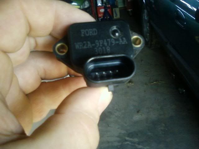 By comparison, here is the 1-bar TMAP as used from AU2 through BF. I've NFI what the FG sensor is like however. Anyone who's pulled down an FG and has photos and/or part number is more than welcome to round out the roundup 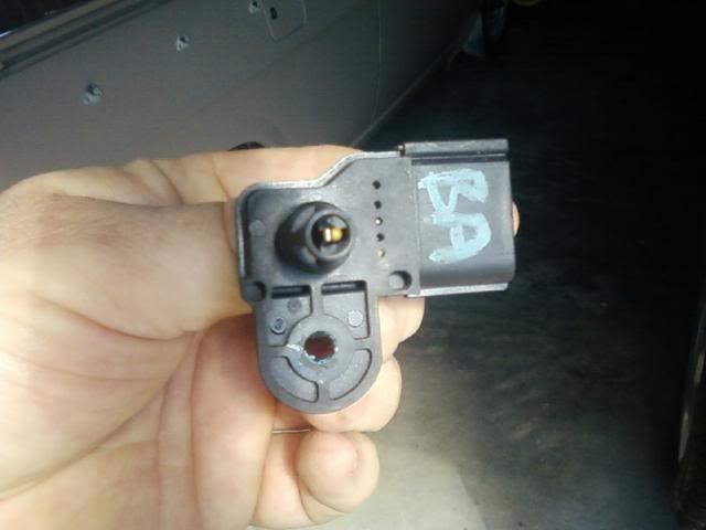 The one pictured comes from a BA, as evidenced by the wrecker's labelling on it. But the part number shown matches the sensor fitted to a complete AU2 BBM pictured further down. The part number prefix, XS6F, is a bit of a mystery too. It doesn't match any Falcon prefix codes I know, so I guess it comes from elsewhere in the Ford world. Probably a Euro Ford, given that it's made in Germany and has what appears to be a Bosch part number on it as well. 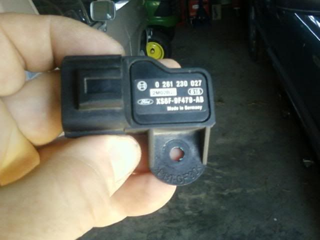 Moving on to the XR6T 2-bar TMAP, which is distinguishable from the last unit by its part number and wiring connector. 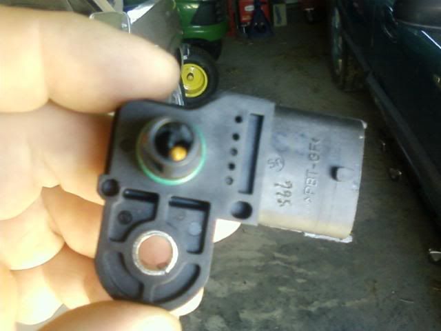 The 3R23 part number prefix shows this is a part first used on BA series 1 vehicles. 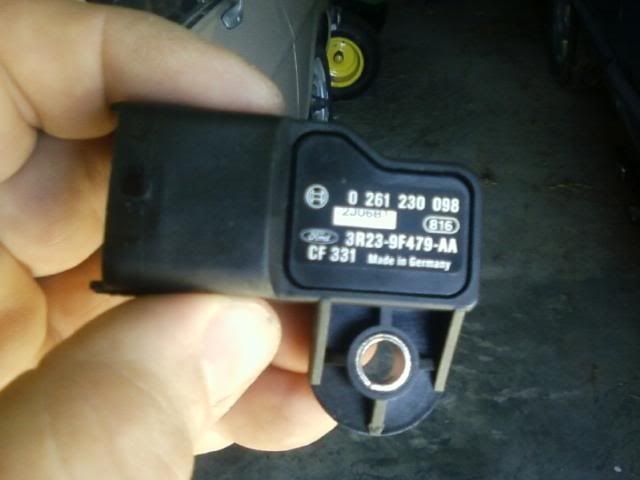 And here are the connectors on the AU2+ sensors, side-by-side for easy comparison. Turbo on the left, NA on the right. On the Turbo sensor, the pins are labelled 4 3 2 1 above the pins, the NA sensor has them labelled 1 2 3 4 below the pins. The shadow on the right just hides the 4 in the NA sensor. 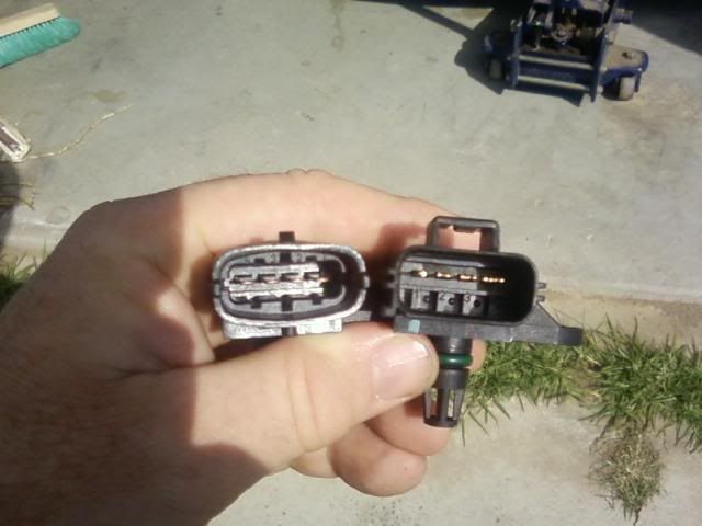 This is a complete AU2 BBM, showing that the TMAP is mounted under the throttle body in the top half of the BBM, as in the AU1. 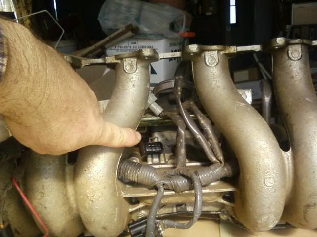 Here is as much of a close-up as I could get on a cheap phone. 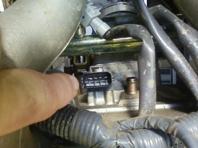 More or less the same shot, with the plug connected. 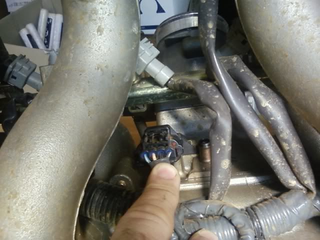 And a close-up of the AU2+ NA plug to get a look at the wires, which again are Black/White, Black/Yellow, Orange/Black and Blue/Yellow, but from right to left, so they are reversed compared to the AU1. 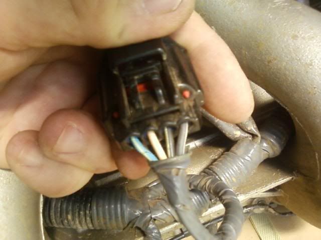 ATM I don't have any B-series wiring diagrams, so I can't say if the wiring colour scheme is carried over from the AU. I should be getting an XR6T wiring plug soon though. It will have a wiring tail on it, which will help. The AU wiring diagrams I have show the uses for the wires are:
So it looks like the pinouts go: -------------------------------------AU1---------AU2+ NA---------XR6T Black/White_________________A__________4____________1 Black/Yellow ________________B__________3____________2 Orange/Black________________C__________2____________3 Blue/Yellow _________________D__________1____________4 The last piece of the puzzle is that the AU1 upper BBM is interchangeable with the AU2/3 upper, allowing fitment of an XR6T TMAP to an AU1 as a prerequisite for a 2-bar tune on a boosted AU1.
_________________ AU1.5 Wagon, Raptor ProStreet kit, Pacemaker 4499's with 3" collector, 3" metal cat, 3" pipe, Pex BSO660 & BSO439, BA brakes, Sprintgas mixer LPG system, Airod variable-venturi mixer... stealth FTW Sniper tuned! |
||
| Top | |
||
| phillyc |
|
||
|
I think this should be made a sticky! Great post Sly
|
||
| Top | |
||
| sly |
|
||
|
More info. Here is the MAP output curve as printed in the Haynes manual for the AU1:
15kPa (absolute pressure)_____ 0.3V 30kPa _____________________ 1.0V 50kPa _____________________ 2.0V 70kPa _____________________ 3.0V 90kPa _____________________ 4.0V 105kPa ____________________ 4.8V The Gregory's manual covering AU1, 2 & 3 provides the exact same output curve for all series. And for comparison's sake, here is the XR6T sensor curve from Dansedgli's BA manual: 10kpa - 0.3v 50kpa - 1.0v 100kpa - 1.9v 150kpa - 2.8v 200kpa - 3.7v It looks like there's a bit of headroom there, maybe the XR6T item actually ranges up to 2.5 or 3 bar?
_________________ AU1.5 Wagon, Raptor ProStreet kit, Pacemaker 4499's with 3" collector, 3" metal cat, 3" pipe, Pex BSO660 & BSO439, BA brakes, Sprintgas mixer LPG system, Airod variable-venturi mixer... stealth FTW Sniper tuned! |
||
| Top | |
||
| sly |
|
||
|
Galapogos01 had me baffled the other day when he wrote here --> post1226326.html#p1226326 that:
{USERNAME} wrote: Also, as a side note, the 1.5 cars use AU1 MAP and temp sensors, which use a different transfer to the AU2. Though you can run an AU2 bin in them, it won't work properly due to the difference in sensors. as all of the info I had seen so far suggested that the transfer functions were the same in AU1 and AU2/3. But then I recalled a PM that a Sniper user from these forums (and AFF) had sent me some 12 months ago, wherein he said: Quote: My (AU1) has A/D counts 0.000 = 0.00 In HG 61.4375 =4.33 In HG 983.0000 = 31.32 In HG 1023.0000 = 31.99 In HG My (AU2) has A/D counts 0.000 = 0.00 In HG 60.0000 = 2.13 In HG 897.0000 = 31.99 In HG 1023.9844 = 31.99 In HG Long story short, converting "A/D counts" to volts (1024 = 5V) and inHg to kPa shows that his AU1 is within a whisker of mine, and his AU2's transfer table looks like: 7kPa ___________ 0.3V 108kPa _________ 4.4V 108kPa _________ 5.0V Remembering that the AU2 TMAP is closely related to the XR6T TMAP, and that as speculated earlier it looks like the XR6T unit may in fact be a 2.5 bar sensor, I'd take a punt on the full spec for the XR6T TMAP being: 10kPa __________ 0.3V 50kPa __________ 1.0V 100kPa _________ 1.9V 150kPa _________ 2.8V 200kPa _________ 3.7V 250kPa _________ 4.6V 250kPa _________ 5.0V If anyone can prove or disprove this, please put your hand up! And just for the fun of it on a rainy Sunday afternoon, here's a plot of the 3 transfer curves that might be easier to take in than all the numbers. 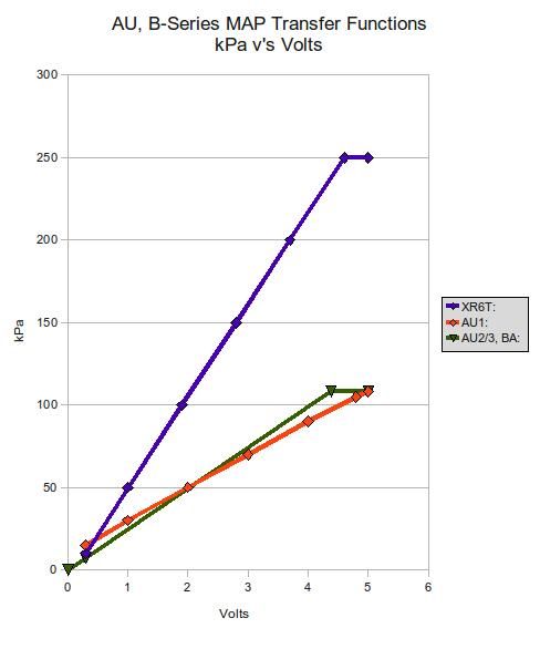
_________________ AU1.5 Wagon, Raptor ProStreet kit, Pacemaker 4499's with 3" collector, 3" metal cat, 3" pipe, Pex BSO660 & BSO439, BA brakes, Sprintgas mixer LPG system, Airod variable-venturi mixer... stealth FTW Sniper tuned! |
||
| Top | |
||
| Hillbillys_curse |
|
||
|
silly question will the series 2 au comp run with the ba xr6T map sensor without a tune ? cause i just fitted one onto my series 2 ute and it wouldnt start but once we put the standard au map back in it run again ?
|
||
| Top | |
||
| sly |
|
||
|
Absolutely correct - it's a silly question
Check out the graph above. At atmospheric pressure (1000 millibars = 1000 hectopascals = 100 kPa) the AU2 computer is expecting to see approx 4.0v. The XR6T TMAP supplies 1.9v. Why is this important? Because the computer is most likely programmed to enter cranking mode when the ignition is turned on AND engine rpm is zero AND manifold pressure is atmospheric pressure. The 1.9v supplied by the XR6T TMAP at normal atmospheric pressure corresponds to the voltage supplied by the AU2 TMAP when the air pressure is around 450hpa... which occurs at roughly 6000m / 20,000ft above sea level, or nearly 3 times the height of Mt Koszciusco. The computer is most likely calibrated to assume this represents a failed TMAP sensor. But even if not, the fuel supplied while cranking would be less than half of normal... probably not enough to start the engine. It would be an interesting exercise to fit the XR6T TMAP to a stock AU2/3 and see if it will fire with the help of some Aerostart. If you can start it, it should idle, but will lean out to buggery (and probably stall) if you try to rev it. OTOH, the graph suggests that a stock AU2/3 computer MIGHT run with an XR6T TMAP and injectors that deliver roughly twice the fuel as the stock AU 19lb injectors... say 36lb injectors with a 4bar fuel reg from an XR6T, or 42lb injectors with the stock AU reg. It probably wouldn't idle though, and the ignition timing would be wrong off-idle. So, while you might be able to force it or trick it to run under some conditions, you won't get it running nicely without a tune.
_________________ AU1.5 Wagon, Raptor ProStreet kit, Pacemaker 4499's with 3" collector, 3" metal cat, 3" pipe, Pex BSO660 & BSO439, BA brakes, Sprintgas mixer LPG system, Airod variable-venturi mixer... stealth FTW Sniper tuned! |
||
| Top | |
||
| TROYMAN |
|
||
|
im curently turboing my au 1.5, having the expected issues with voltage going over 5v at around 3psi, it appears the voltage table cannot be manipulated enough to allow boost..
so i just wired in a series 2 map sensor and the car starts and runs fine on the s2 t map, so it would be fair to assume that the xr6t map will work on the au1 ecu obviously with a tune??.. |
||
| Top | |
||
| SWC |
|
||
|
Quick turn around on the MAP sensor Troy.
Are you going to fit the AUII upper BBM or go with looking at the E series MAP? |
||
| Top | |
||
| TROYMAN |
|
||
|
e series map didnt work, i tried this afternoon..e series is frequency based where the au1 is voltage based same as the au2 sensor ..
its currently set up externally using vacuum from brake booster hose for testing.. if i can use the xr6t map then ill swap bbm upper to a series 2.. |
||
| Top | |
||
| sly |
|
||
|
What are you using to tune it Troy?
_________________ AU1.5 Wagon, Raptor ProStreet kit, Pacemaker 4499's with 3" collector, 3" metal cat, 3" pipe, Pex BSO660 & BSO439, BA brakes, Sprintgas mixer LPG system, Airod variable-venturi mixer... stealth FTW Sniper tuned! |
||
| Top | |
||
| sly |
|
||
|
What are you using to tune it Troy?
_________________ AU1.5 Wagon, Raptor ProStreet kit, Pacemaker 4499's with 3" collector, 3" metal cat, 3" pipe, Pex BSO660 & BSO439, BA brakes, Sprintgas mixer LPG system, Airod variable-venturi mixer... stealth FTW Sniper tuned! |
||
| Top | |
||
| TROYMAN |
|
||
|
{USERNAME} wrote: What are you using to tune it Troy? sct xcal3 flash tuner |
||
| Top | |
||
| TROYMAN |
|
||
|
temp fitted an xr6t map sensor, wired up as per mentioned above and it starts and idles great, but thats about it, as soon as it sees any load it dies..
so the map feature needs to be scaled to suit i assume... |
||
| Top | |
||
| sly |
|
||
|
A number of things need to be scaled. The MAP Transfer table won't accept a pressure higher than 32 inHg IIRC, which is mean atmospheric +10%. The VE table won't accept volumetric efficiency greater than 99% in any cell, so you can't simply keep pushing VE up to the limit of the TMAP (which would be 250% in the case of the XR6T TMAP).
I've worked up theoretical base VE and timing tables, based on stock, extrapolated for boost, then scaled back by dividing by 2.5 to fit within the 32 inHg / 99% constraints. I then divide the injector flow rate scalar and cranking injector pulse width table values by 2.5 to maintain parity there. I believe I could alternatively multiply the engine capacity by 2.5 to achieve the same result, but I haven't tried this and don't know if the computer will accept a 10-litre capacity. But this has only been theoretical up to now. I've needed the car ready to go at short notice most of this year, so I haven't played with any of this live. But now the car is a non-runner due to a catastrophic loss of oil pressure & I have to decide what engine to put in to get it going again. An XR6T transplant has been ruled out due to cost and complexity, but I'm still not decided between AU I6 or V8. It'd help if I was sure I'd found all the tables I need to change, or if a commercial tuner said they were willing/able to do a tune to suit. So far 2 Sniper tuners have not even responded to my enquiries... An engine replacement would provide the ideal opportunity to switch the upper BBM and TMAP, but then I don't want to melt a "new" engine in short order due to my amateur tuning efforts.
_________________ AU1.5 Wagon, Raptor ProStreet kit, Pacemaker 4499's with 3" collector, 3" metal cat, 3" pipe, Pex BSO660 & BSO439, BA brakes, Sprintgas mixer LPG system, Airod variable-venturi mixer... stealth FTW Sniper tuned! |
||
| Top | |
||
| TROYMAN |
|
||
|
all done, the au1 is running the xr6t 2 bar map sensor via flash tune.
not sure if this is right or not, but going on the voltage from the xr6t map it almost halved the fuel by aprox 50% off idle or from 50kpa so the larger injectors more than doubled the flow so it worked out.. from what the tuner told me he put injector scale back to 20lb from where it was to run std map with 80lb injectors, and adjusted fuel map to suit.. its still mounted bodgy via vac hose for map only as i still have to change the upper manifold to suit. also found ba n/a uses same map sensor and plug as au2/3, i think this was mentioned above. fg n/a plug is the same as the ba xr6t plug. and fg turbo has a different map and plug to above.. im not 100% as i havent physically tried it, but it almost looks like the series 1 au map plug could fit ba xr6t map??? ill find out soon enough... |
||
| Top | |
||
| Who is online |
|---|
Users browsing this forum: No registered users and 0 guests |