

|
| galapogos01 |
|
|||
Posts: 1139 Joined: 27th Feb 2005 Ride: Supercharged EF Fairmont Location: T.I. Performance HQ |
{USERNAME} wrote: I've managed to find a forum that has a few big name head porters engine builders, from the USA as members. Any chance of posting a link? Very keen to see your work on these heads. I'm also keen to see how it relates to the intake manifold -- if you took the port out to 39mm is there enough meat in the intake? Can you get the intake runners that wide all the way around a BBM or long manifold? Cheers, Jason
_________________ {DESCRIPTION} - {DESCRIPTION}, {DESCRIPTION}, {DESCRIPTION}, {DESCRIPTION} and more! |
|||
| Top | |
|||
| tickford_6 |
|
||
Posts: 6449 Joined: 11th Nov 2004 |
{USERNAME} wrote: {USERNAME} wrote: I've managed to find a forum that has a few big name head porters engine builders, from the USA as members. Any chance of posting a link? Very keen to see your work on these heads. I'm also keen to see how it relates to the intake manifold -- if you took the port out to 39mm is there enough meat in the intake? Can you get the intake runners that wide all the way around a BBM or long manifold? Cheers, Jason I don't believe the factory intake manifolds would be suitable for use on an engine that could make use of the sort of airflow that size port 'should' be capable of. I would say its venturing into the realm of a custom IR intake and would probably mean a set up from 45mm to 48mm TBs. I was about to sit here and type for 10 mins (going off an a tangent) But what I should be doing to sorting out the port moulding guide. So I'm off to do that. |
||
| Top | |
||
| tickford_6 |
|
||
Posts: 6449 Joined: 11th Nov 2004 |
Port moulding
What you will need. 500g fast set silicon. In this case I am using Pinkysil Bought online from http://www.amcsupplies.com.au Small amount of dish liquid (free mould release) A kitchen scale A mixing cup and a mixing spoon. 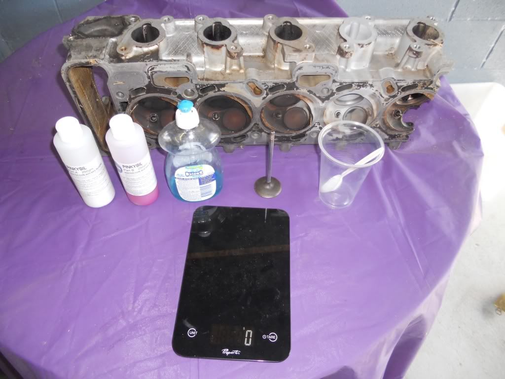 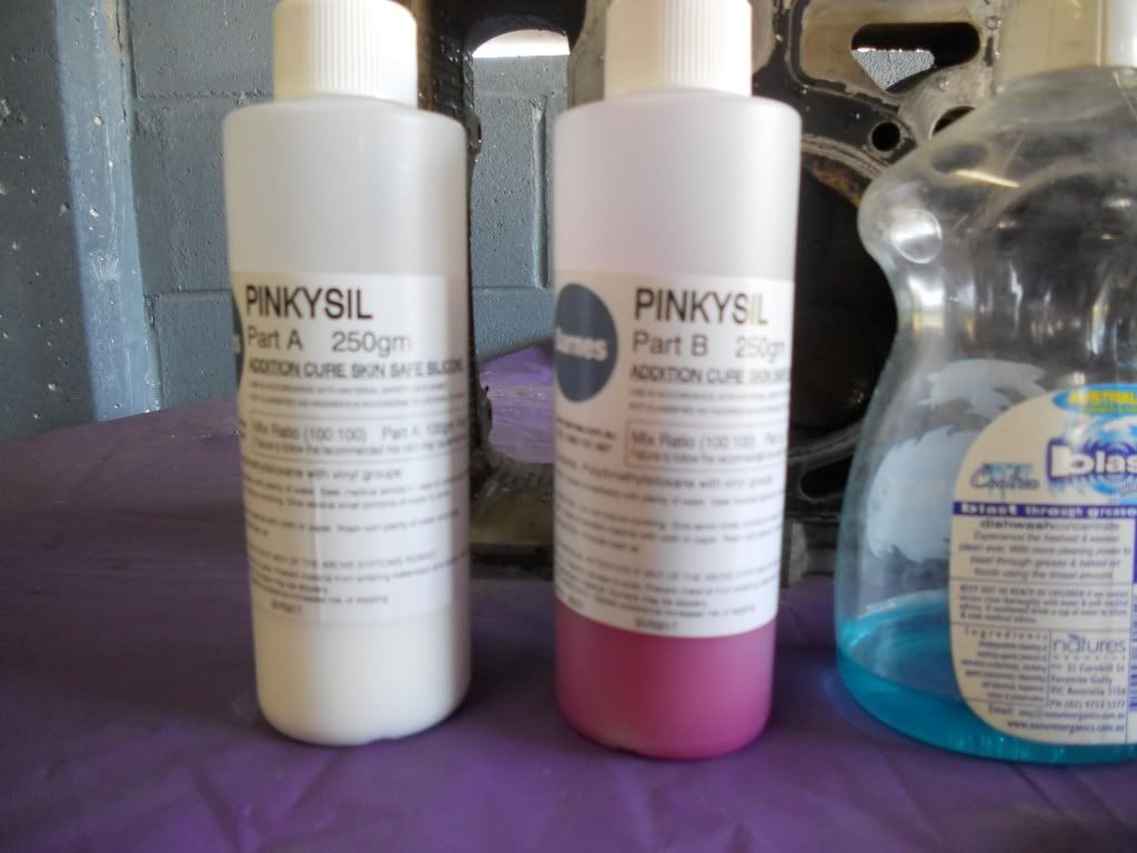 First step is clean the port and valve you are going to mould. Leave the valve stem seal in place as it will help to hold the valve in place. Place the head on a plastic covered table with the exhaust ports facing down, You want the head reasonably level. 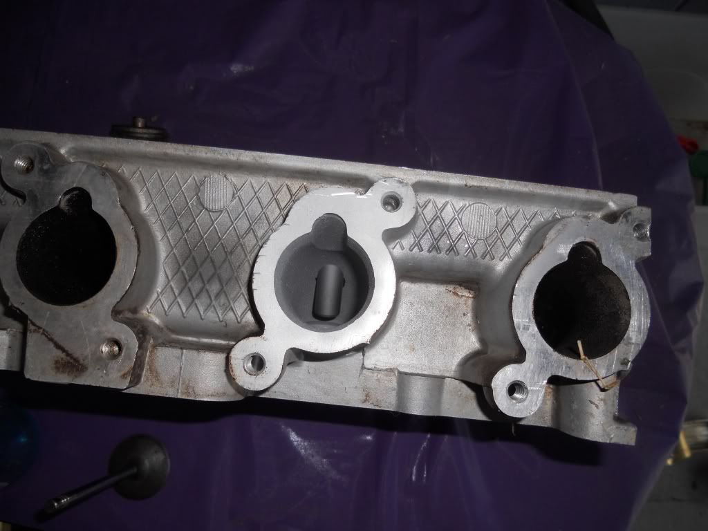 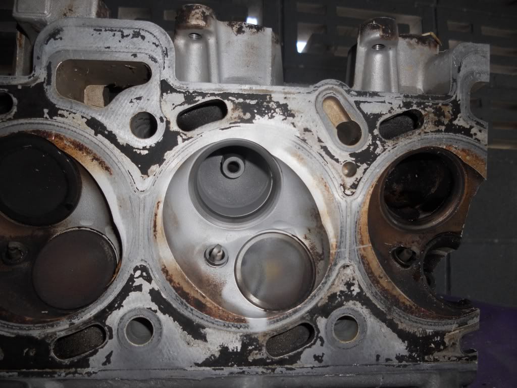 Put a small drop of dish liquid on your finger and coat the back of the valve and about 2cm of the stem. Also coat as much of the port and valve guide as you can. In doing this you do not want to wet the port with dish liquid, you only want a 'dry' coating. Sorry no pic of this process. Once done install the valve making sure it is seated firmly. 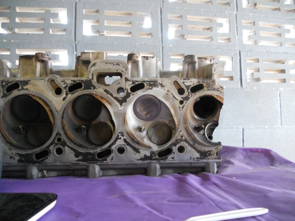 Place the cup on the scale. 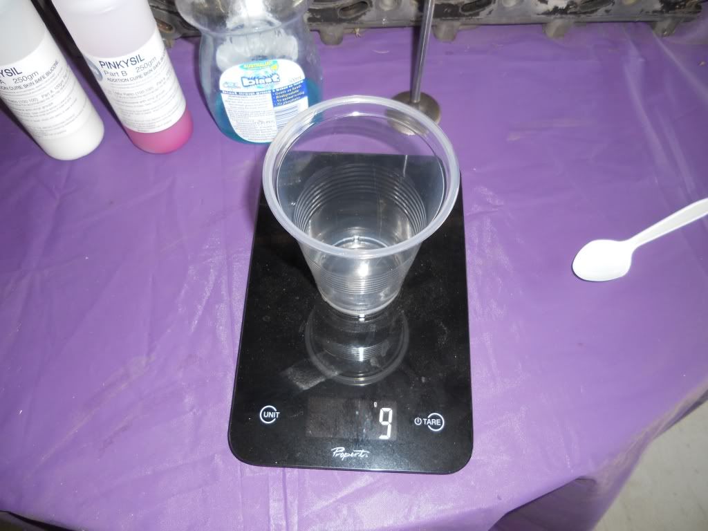 and then zero the scale 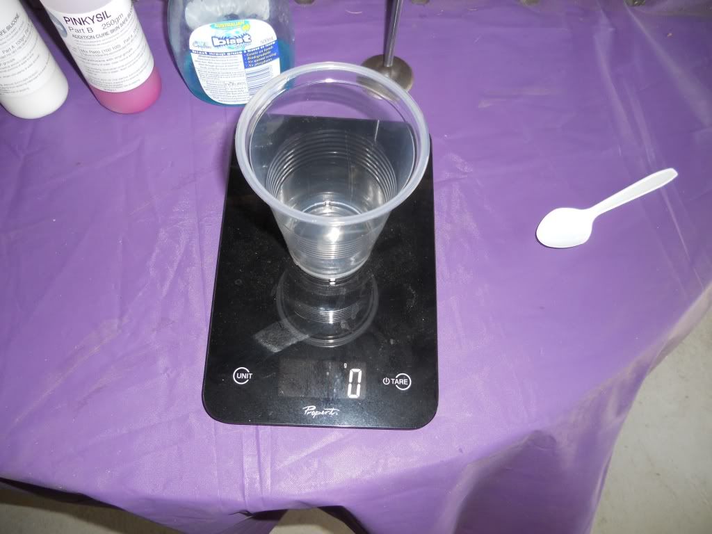 Slowly pour in 80 grams of PART A 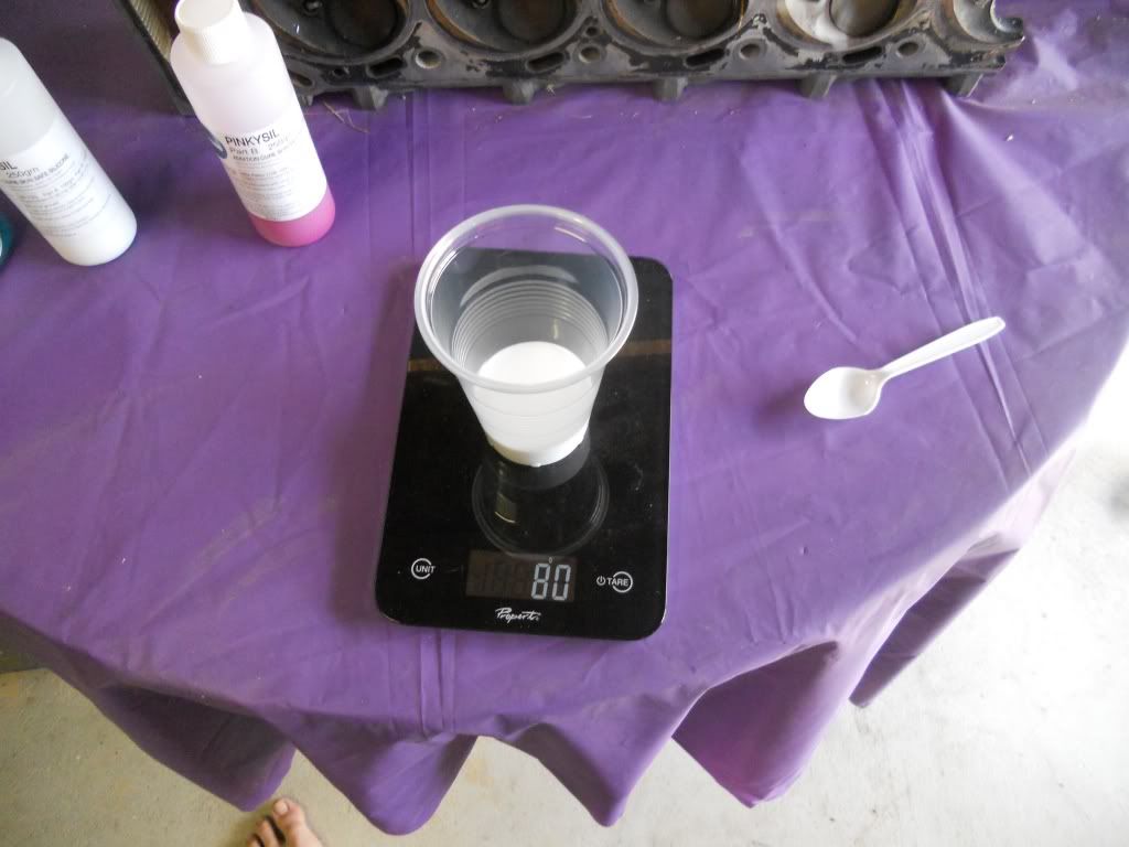 Then aero the scale again. Slowly pour in 80 grams of PART B Mix thoroughly to get an even, consistent coulor. At this point as we are using a fast set silicon you only have at most ONE minute to get the mixing done other wise the silicon will start to set and you will be rushing to pour the now thick lumpy silicon before it's wasted. TRUST ME Once mixed pour the silicon slowly into the port until full 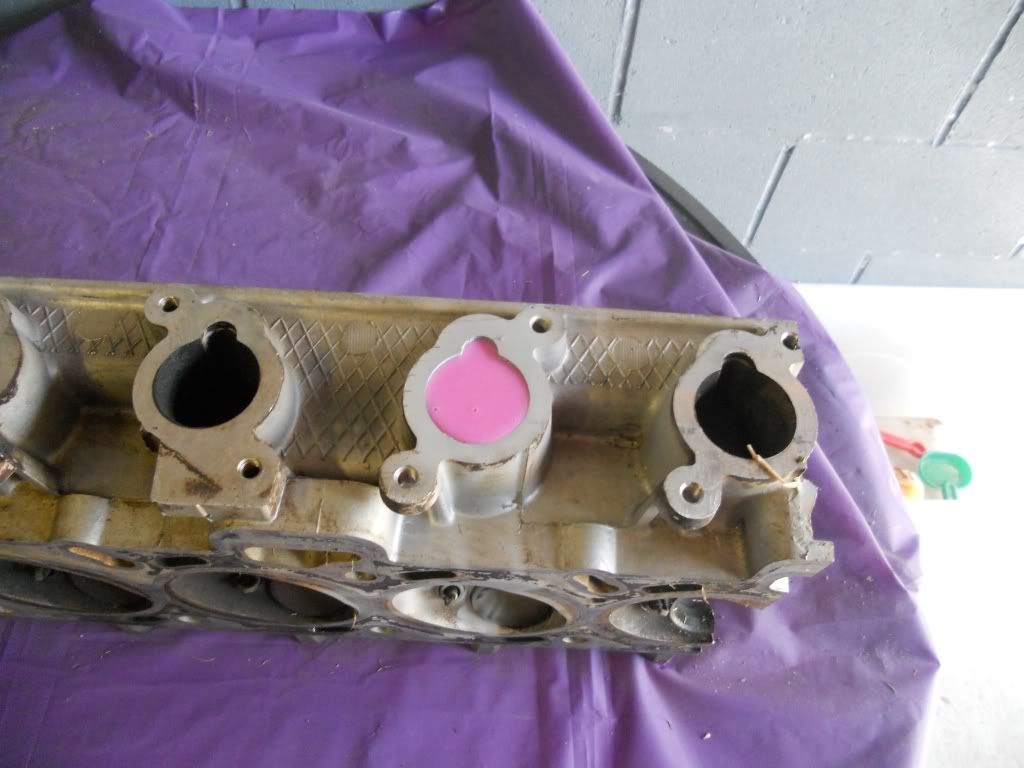 Depending on the head you are moulding, you'll have a little left over 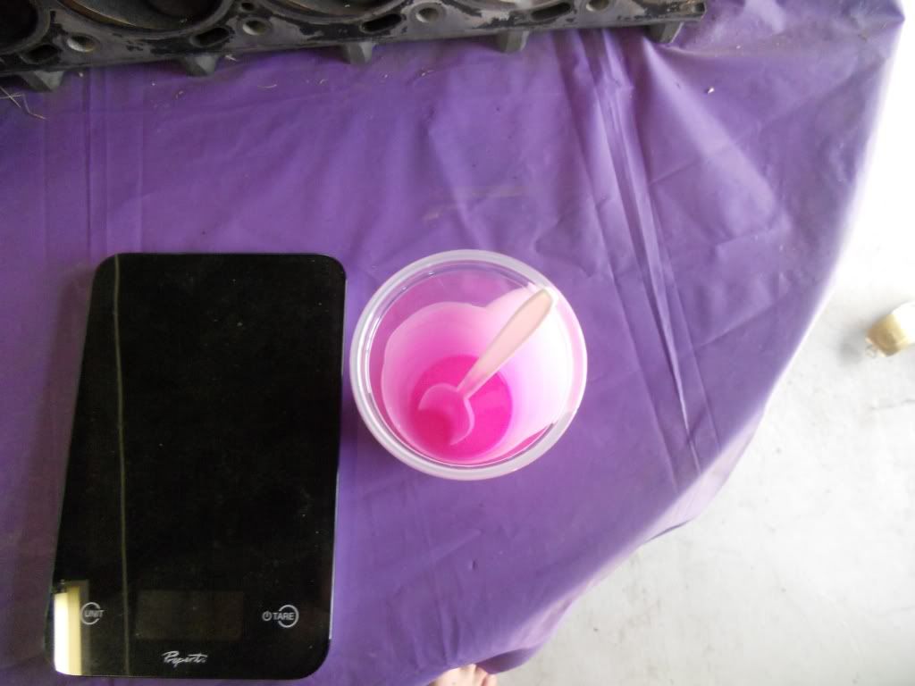 If you have a lead sinker moulds, now would be a good time for making some bright pink slingshot ammo De-moulding After 20 mins the mould is ready to come out. Give the valve a tap to knock it loose and remove it. 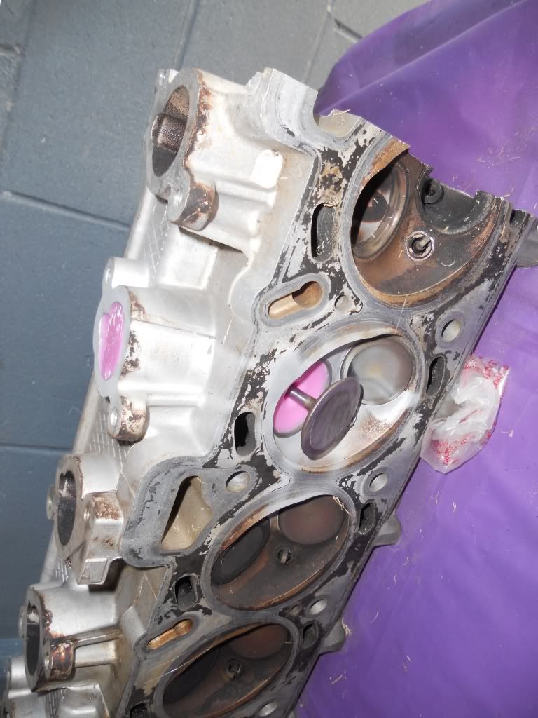 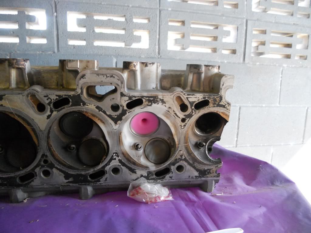 Insert a flat screw driver to gently pry the mould away from the port walls, do this right around the mould at both ends. 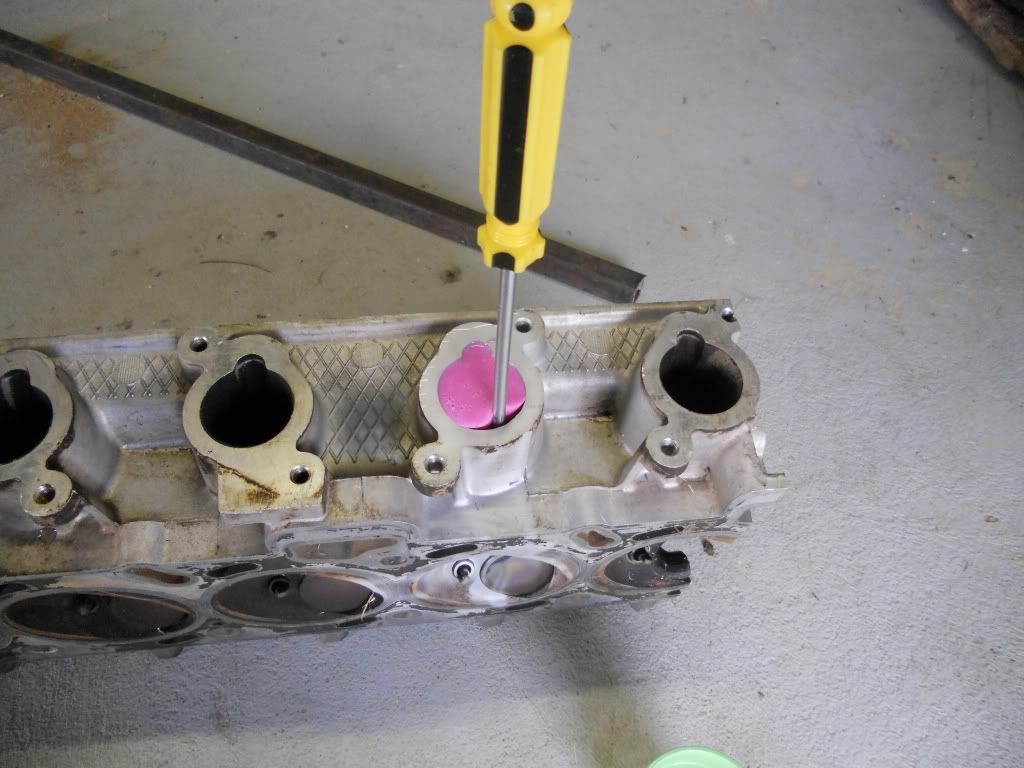 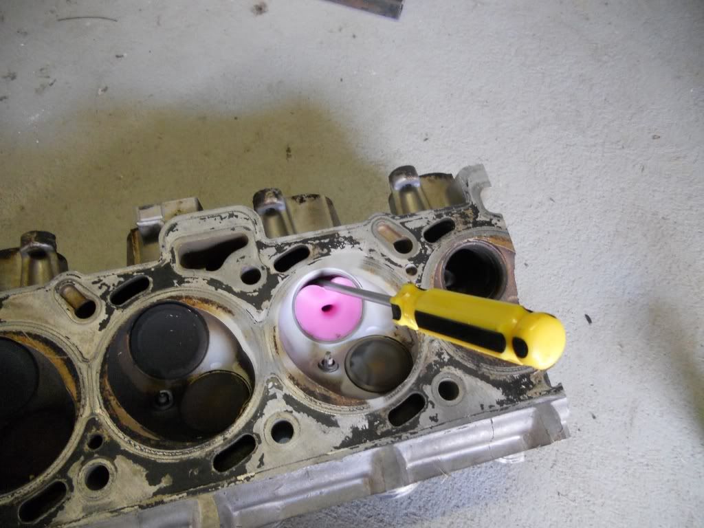 Mix a small amount of water and dish liquid and with the screw driver still inserted tip some into the gap, again all around and at both ends working the mould to get all of it soaked. 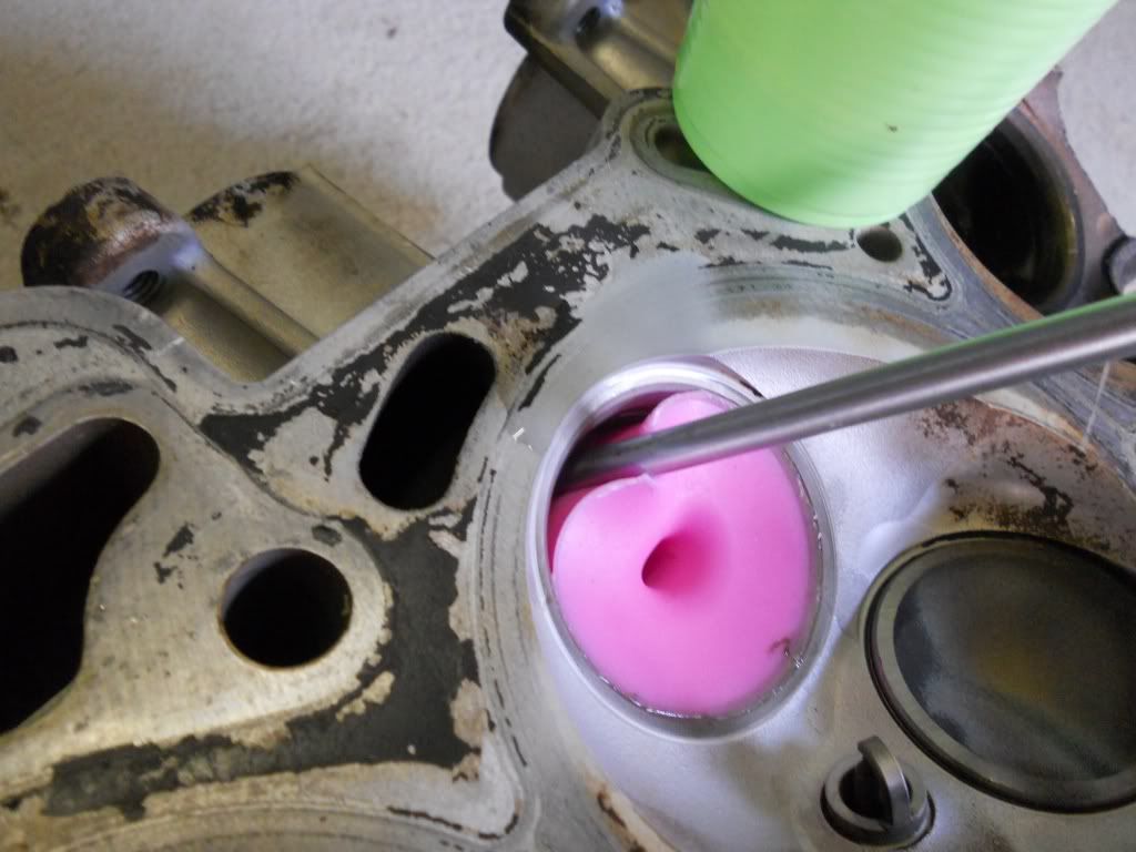 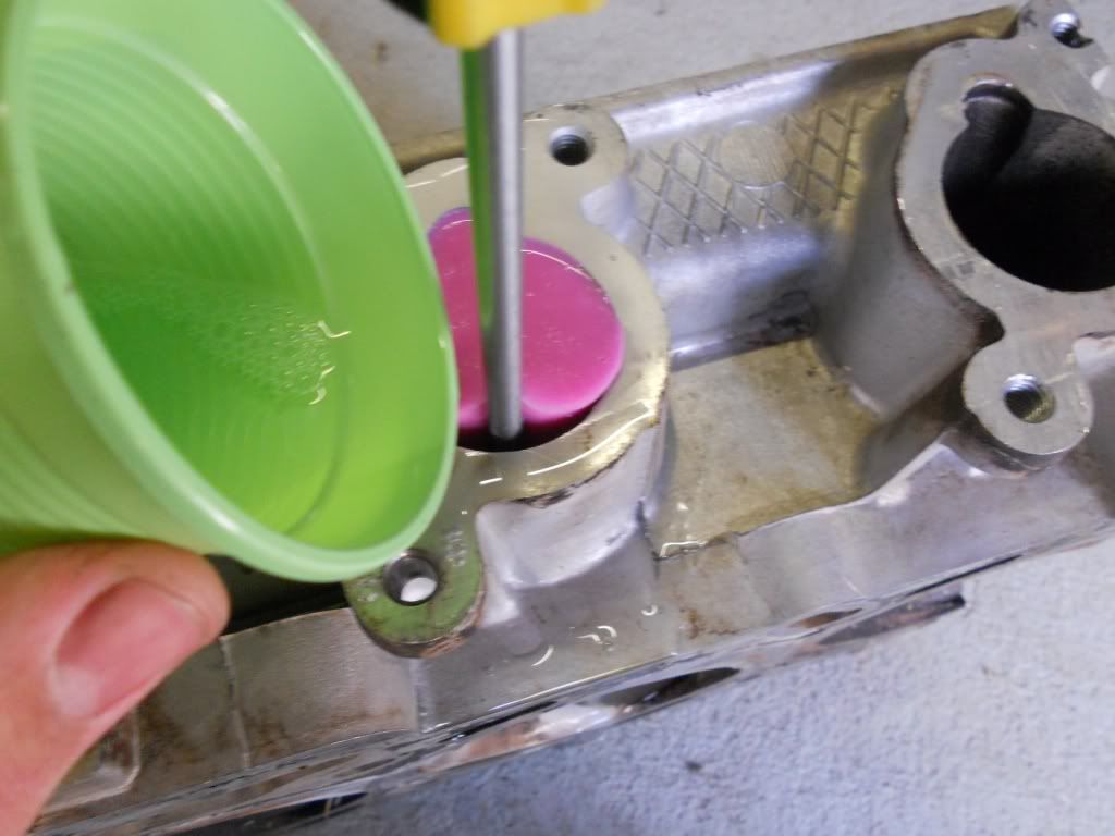 Now push from the manifold end with handle of the screw driver and push the mould out. This may take a fair amount of force. 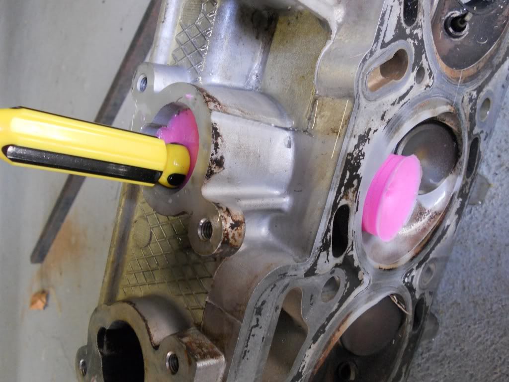 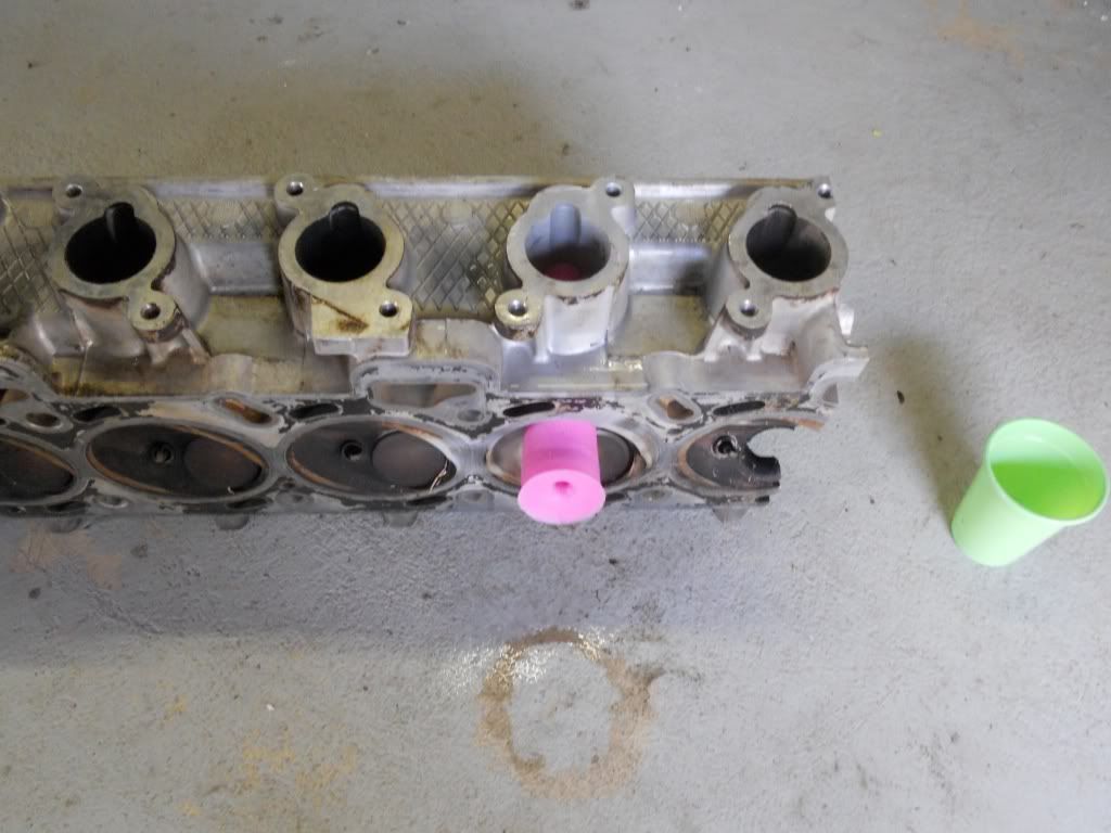 The finished mould 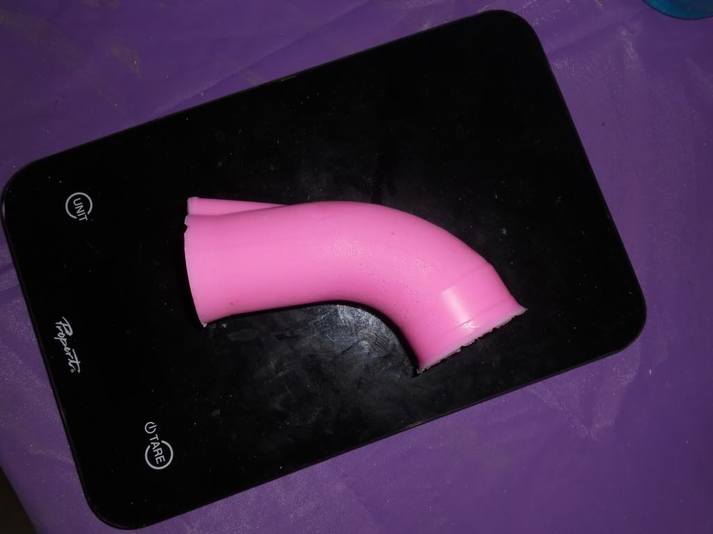 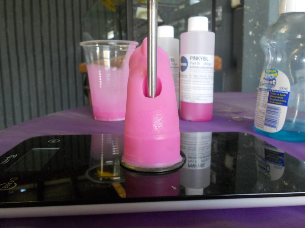
|
||
| Top | |
||
| EBXR8380 |
|
|||
|
Has digitising a GOOD port job and CNC machining like
http://www.bulletcylinderheads.com.au/index.php We did a set of Lexus 4.0 V8 heads. Yes had to cut up a perfect good head.. But got gains from memory 165 CFM to 190 with std valves.. We then fitted 2mm oversize and achieved just short of 220 at .450 lift.. On 4 valve head.. With CNC porting every chamber & head is identical.. Makes for better tuning... 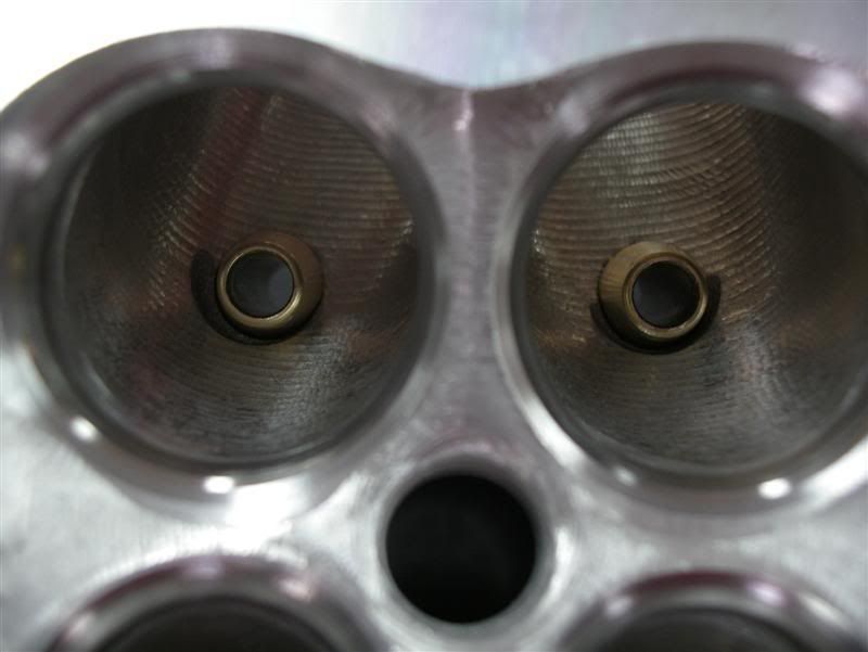 ;  Assembled with Ferrea 2J valve valves and Crower springs.. 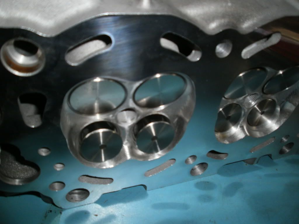
_________________ As in ZOOM 126 edition Last edited by EBXR8380 on Sun Sep 25, 2011 9:33 pm, edited 1 time in total. |
|||
| Top | |
|||
| tickford_6 |
|
||
Posts: 6449 Joined: 11th Nov 2004 |
{USERNAME} wrote: Has digitising a GOOD port job and CNC machining like http://www.bulletcylinderheads.com.au/index.php We did a set of Lexus 4.0 V8 heads. Yes had to cut up a perfect good head.. But got gains from memory 165 CFM to 190 with std valves.. We then fitted 2mm oversize and achieved just short of 220 at .450 lift.. On 4 valve head.. With CNC porting every chamber & head is identical.. Makes for better tuning... How much did you pay to have your port digitised and reproduced? |
||
| Top | |
||
| EBXR8380 |
|
|||
|
$2500 BUT a SOHC six would be MUCH cheaper...
There are other CNC places around now too...
_________________ As in ZOOM 126 edition |
|||
| Top | |
|||
| tickford_6 |
|
||
Posts: 6449 Joined: 11th Nov 2004 |
A single valve port should be easier to digitise and easier to write a tool path for, So it should come in much cheaper, and being only one head there is less labour involved as they would only need to set up one head in the machine.
It's something i'll store away for use when a port shape worthy of CNC reproduction is found. |
||
| Top | |
||
| tickford_6 |
|
||
Posts: 6449 Joined: 11th Nov 2004 |
I was asked this on a post I made on Boostedfalcon.
Though I would add it in here as I kind went on a bit and off a kind of related tangent, Figured te info was still good though. Quote: Wow pretty cool s**t. What have been your findings so far? That particular port (AU1 VCT) narrows at the short turn and has the valve guide protruding at the same point creating a choke point. The choke point is what limits flow at high lifts, below roughly .350" lift the shape of the valve, seat ect is what controls flow. Until the choke is fixed puting grinding burr or paper roll anywhere between the port entry and the start of the short turn is waste of time. For the DIYer the time and money best spent is removing the guides and shortening them by 3mm (using the shortest one as a guide to modifying the others) then tappering them down. 30 degree back cut on the valves, taking the seat width down to 80thou and then having the the seat in the head cut to make the contact area right the in the centre of the seat on the valve. A good machine shop will know what you are talking about. If you must grind something, widen the port around the guide and the blend all of the rough maching in the bowl of the port. For beginners the blending is best done with a flap wheel as it's hard to make big mistakes with them, then take the pollish off with a 60 grit cartridge roll. That's about all I would recomend a beginner does on any of the I6 heads. |
||
| Top | |
||
| KWIKXR |
|
|||
|
Good stuff there tickford_6, might have to get me some of that silicon and make a few moulds when I get back to work on my 91AA head.
{USERNAME} wrote: If you must grind something, widen the port around the guide I'd definitely concur with this, even more-so with the earlier heads (ea-el non-tickford) which have the guide bosses built up around the guide. It reduces the CSA of the port by a great deal. Here's a few snaps of a bit of work I've done around the guides on my 91AA head so far, very slow work in progress and still have a fair bit to do. I made a start by getting all the guides removed.. On the intake side I widened the walls either side of the guide and tried to cut back a bit of material at the 10 and 2 positions to get a bit more area around the guide. Started cutting down and reshaping the guide bosses too, still needs a bit more work though.. The replacement valve guides will be shortened a few mm's and also have a taper put on the protruding part to take up less CSA (as tickford_6 has mentioned) Intake.. 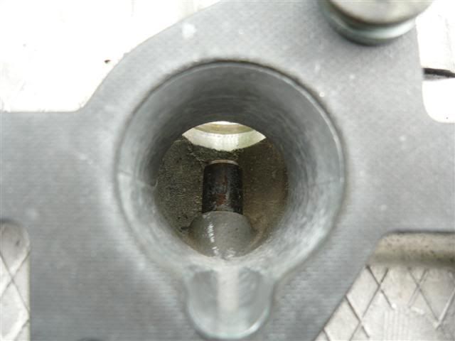 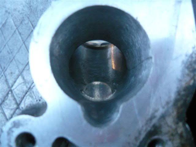 The exhaust side was a little harder, especially when one of the guides that was removed took out half the guide boss along with it so had to cut them all back and reshaped them to get them all near matching again.. Walls were widened, and guide bosses were shaped to try give a 'teardrop' effect'. Still needs a fair bit of work here though, need to round off certain areas of the guide boss but don't have the right burr for the job at the moment.. Still not sure what I'll do with the guides on the exhaust side but was going to have the guides inserted so they line up with the highest point of the guide boss, then smooth out and round off the exposed part of the guide so the air flows around it smoothly.. Exhaust 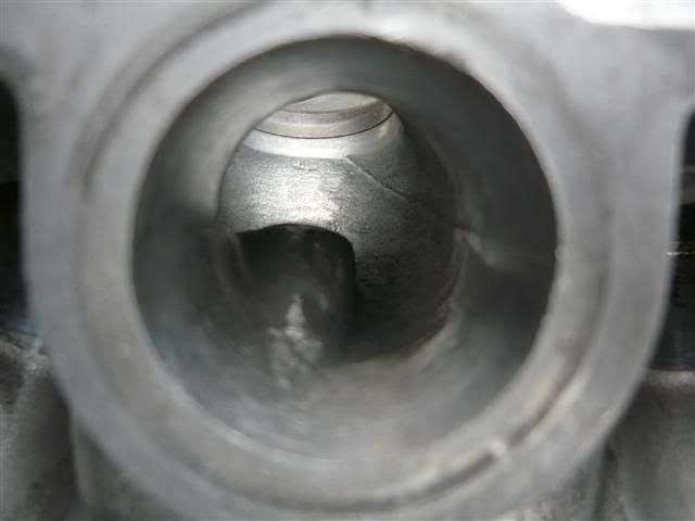 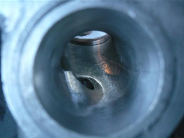
|
|||
| Top | |
|||
| tickford_6 |
|
||
Posts: 6449 Joined: 11th Nov 2004 |
KWIKXR
With your exhaust port, Just take the guide out completely. By the looks of it enough has broken off that there isn't enough left to do any thing useful with. With you intake guide boss, leaf just enough of it in front of the guide insert to give a nice radius from the roof onto the insert and narrow it as much as you can then try tear drop it in to the bowl. You could go wider on the roof around the guide too. You'll need to do that after the insert has been put back in or you'll risk cracking the boss. Lay the short side back a few mm. |
||
| Top | |
||
| KWIKXR |
|
|||
|
Awesome, thanks for the advice mate! I'll definitely have to work on those areas when I get back to the porting. Cheers
|
|||
| Top | |
|||
| tickford_6 |
|
||
Posts: 6449 Joined: 11th Nov 2004 |
Ok just an update of where I'm at.
Autospeed flow a STOCK AU head at 117cfm at .500" lift. They tested it at 10" H2O To convert from 10" to 28" we mutiply by 1.67. That puts the AU head 195.39cmf@.500" lift tested at 28" H20. Now if we work back to the CSA of the port at the choke point in the turn. The CSA at this point is 864mmsq. Through some math we can use that to show us what flow the CSA will support with an air speed of 350fps. When I do this I get 195.494CFM @ 28" H2O. (those findings prove the formula) IF we then work our way through the port, The port proper can support 230cfm The seat area can support 281cfm Curves, shape change, and other things will effect the flow. Meaning if you didn't touch the seat area at all and brought the rest of the port to a point that it could flow 280cfm you probably will not get 280 through the seat. It should by now be clear that first of all, doing the back yard polish job is a waste of time. second If we want big flow the port proper is TOO SMALL. |
||
| Top | |
||
| tickford_6 |
|
||||
Posts: 6449 Joined: 11th Nov 2004 |
This a calculator I quickly threw together tonight.
Fill in the yellow cells. "lost area" is area lost to the valve guide/boss. Stem area is just that, the area taken up by the valve stem. use this once you are past the guide. Lost area and Stem area will automatically be subracted from the CSA. In the red section you can enter a desired flow and you will be given the minimum area you need to achieve that flow with an air speed of 350fps
|
||||
| Top | |
||||
| Sierra |
|
|||
|
{USERNAME} wrote: Looking like the valves will come in at about $60 each, But I still have some stuff to sort out before it final. Hey tickford_6 ... any updates on these valves? ... will the availability be a one off situation or permanantly available? Also ... are a flat backed, wasted stem configurations an option for increased flow on these heads?
_________________ 95 EF XR6 Manual |
|||
| Top | |
|||
| tickford_6 |
|
||
Posts: 6449 Joined: 11th Nov 2004 |
{USERNAME} wrote: {USERNAME} wrote: Looking like the valves will come in at about $60 each, But I still have some stuff to sort out before it final. Hey tickford_6 ... any updates on these valves? ... will the availability be a one off situation or permanantly available? Also ... are a flat backed, wasted stem configurations an option for increased flow on these heads? I need to send a sample of the stock valves and locks to the manufacturer to be able to guaranty compatibility with the stock locks and retainers. The only other option is to order them with a single groove and have a retainer made to suit and off the shelf lock. Which at the moment will push cost either way. I'm just holding off following it up any further untill I need a set myself. Once that's done I'll offer them on an order by order basis. |
||
| Top | |
||
| Who is online |
|---|
Users browsing this forum: No registered users and 0 guests |