|
| gogetta |
|
|||
|
top quality thread!! great work dysfer!!....
its good to see people sharing ideas and helping each other which is the spirit of a good forum.... we dont all have thousands to spend on off the shelf parts... it may not work straight away but youll learn heaps by actually doing something... keep going, just ignore the negative and unhelpful advice...
_________________ |
|||
| Top | |
|||
| tickford_6 |
|
||
Posts: 6449 Joined: 11th Nov 2004 |
Brockyb8 wrote: See now you just being silly im just saying until u made a set of these for this specific specification all it is just maths. Oplease spent almost a year and a half perfecting these . Then i spent another year on them . We then decided to build our own . What els did you expect? you got offended because you took it personally. then you start being rude. what ever dude. |
||
| Top | |
||
| Brockyb8 |
|
||
|
tickford_6 wrote: Brockyb8 wrote: See now you just being silly im just saying until u made a set of these for this specific specification all it is just maths. Oplease spent almost a year and a half perfecting these . Then i spent another year on them . We then decided to build our own . What els did you expect? you got offended because you took it personally. then you start being rude. what ever dude. How could i get offended lol u make me laugh mate . I offered some personal experience you gave your opinion and i just said that its something that he will learn from this whole experience . I wish dysfer all the best and if u want some help mate send me a pm .
_________________ YEAH ITS A BROCK, AND YEAH HE DID DRIVE A FORD
|
||
| Top | |
||
| dsyfer |
|
|||
|
Cheers all, no opinions or suggestions are bad, there is something to be found in all of them.
For me, working it all out, buiding it and getting it working right is where the fun lies, if I wanted just flat out power a plain old turbo kit is easy. Easy is boring and not much of a challenge. Yes I would love to get to 200rwkw, but it is not the main idea behind the project, the project itself is for me. I have found a place with the correct madrel dies and balls to do the bending, so just need to fine tune the shape and cut out some templates on the laser cutter (I love the toys we have at work Any aluminium people here? The guy at the place I bought the tube couldn't tell me, but from the info I have found 6060 is already soft and doesn't need annealing before bending? Can anyone confirm this? |
|||
| Top | |
|||
| dsyfer |
|
|||
|
skidder wrote: dsyfer wrote: Ahh, do you know the formula for how fast they diminish? or which program might list them and let you choose? I was thinking maybe a fluid dynamics flow simulator might be more accurate? Not sure what ticky uses but I had this written down, I think I got it somewhere from the net so unfortunately it is in imperial measurements. L = ((EVCD x 0.25 x V x 2) / (rpm x RV)) - 0.5D EVCD is Effective Valve Closed Duration RV is Reflective Value (ie what order you are tuning to; 1,2,3,4,5...I wouldn't go past 4 though) V is Pressure wave speed (approx 1300ft/s at temperature) D is Runner Diameter (in inches) To calculate EVCD you take the duration of your cam away from a whole cycle rotation of the engine (720 degrees). On top of this you want the pressure waves to arrive before the valve closes and after it opens, so you need to subtract some duration from your cam. I have it written advising of subtracting 20 degrees from smaller cams or 30 degrees from bigger cams (ie, if you have a cam with 300 degrees duration your EVCD would be 720 - (300-30) = 450. Here's an example I did in excel for a cam with 300 degrees duration and a runner diameter of 1.5in. Reflective value on vertical axis and rpm on horizontal, with runner length in inches in the middle. 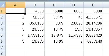 Cheers for this skidder, somehow I missed this post on the first page. |
|||
| Top | |
|||
| skidder |
|
|||
|
That's alright, if anyone else has any other calculations feel free to post them, I won't be offended.
This is just one of many (probably one of the easier ones) I come across. In the end the best place to fine tune is on the dyno, even in top level racing with a team of engineers using full engine mapping and god knows what else that is used to create the 'ideal' manifold changes are still made well after the theoretical manifold is made. *edit, as I am bored today waiting for some waves to show up I went looking through and found some of my notes on where I got the equation and I thought I would share. The reason the top of the equation is multiplied by 0.25 is because the pressure wave has to travel up and down the inlet manifold from the valve 4 times before coming back. Reason being the positive wave created when the valve is shut goes back up and exits the inlet runner, but when it exits it sends a negative wave back down. The negative wave has to travel back down to the valve which it rebounds off (being closed) before exiting at the top of the inlet runner and sending a positive wave of pressure back down which you want to time with the valve opening/being open. The reason it is multiplied by 2 is because the length of your intake runner only has to be half the distance the wave travels (so multiplying velocity by 2 does the same as halving at the end). I also thought I should mention in case I didn't before, when using this to work out runner length it is the whole length from the valve to the end of your manifold. dsyfer wrote: Any aluminium people here? The guy at the place I bought the tube couldn't tell me, but from the info I have found 6060 is already soft and doesn't need annealing before bending? Can anyone confirm this? I am a little shakey on my metals, but I think he is right. From memory 6060/1/3 are pretty easy to bend but require heat treating after depending on application (not for this one though).
_________________ EVL098 wrote: Cramping in the hand from having it on your Wang for an excessive period of time is a definate con. Seriously do people google "f**k up modifications for Fords owned by Jews" and get linked straight to this site nowadays? AU,factory fitted tickford kit/IRS, t5,Sports ryder/KYB: gone. |
|||
| Top | |
|||
| dsyfer |
|
|||
|
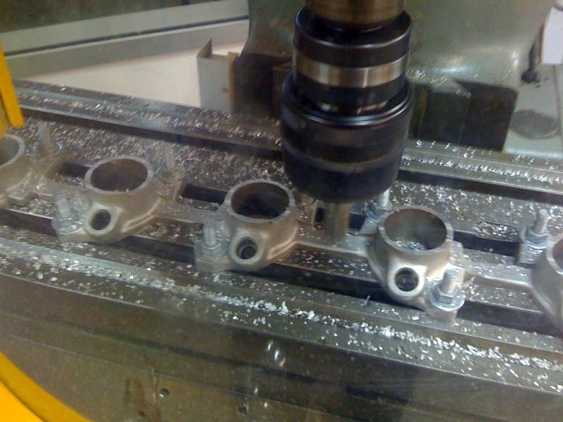
Milled the manifold flange nice and flat today.
 Intake runner shape, to keep runner length at 450mm, and to still stay under the bonnet. 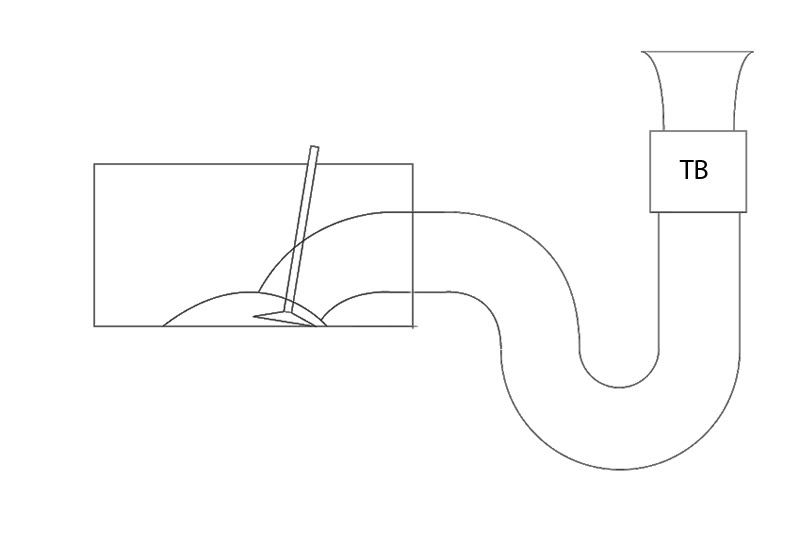 Still playing with the shape, it's hard to measure the engine bay clearances whilst the current BBm is still on the car, might have to make a trip to the wreckers and find an EF without the manifold on. Cam specs: Intake Duration: 276.33 Intake Lift: 540 Exhaust duration: 278.96 Exhaust Lift: 521 LS: 114 |
|||
| Top | |
|||
| 66 coupe |
|
||
|
Thats advertised cam durations? no way they are 050 specs. 005 specs maybe....
Personally i would revise your design, as having the 3/4 S bend as per the image will impede airflow, and probably not be much better than the std intake. You want a straight run to the port, or theres really no point in using ITB's |
||
| Top | |
||
| tickford_6 |
|
||
Posts: 6449 Joined: 11th Nov 2004 |
You should try to have the TBs closer to the port. Part of the benefit of ITBs is the responce, but by placing the tbs where you have you will loose that.
I agree on trying to straighten the runner aswell, |
||
| Top | |
||
| dsyfer |
|
|||
|
66 coupe wrote: Thats advertised cam durations? no way they are 050 specs. 005 specs maybe.... Personally i would revise your design, as having the 3/4 S bend as per the image will impede airflow, and probably not be much better than the std intake. You want a straight run to the port, or theres really no point in using ITB's The bend is what happened when I squished the desired length into the same space as the standard manifold, I'm thinking if I run the throttle bodies at approx 45 degrees I can get it straight without the s bend, just gotta get some decent measurements of the engine bay, got tomorrow off so will work on it then, plus I didn't account for the ram tube length, so the manifold can be slightly smaller as well. Here is the full cam spec sheet: 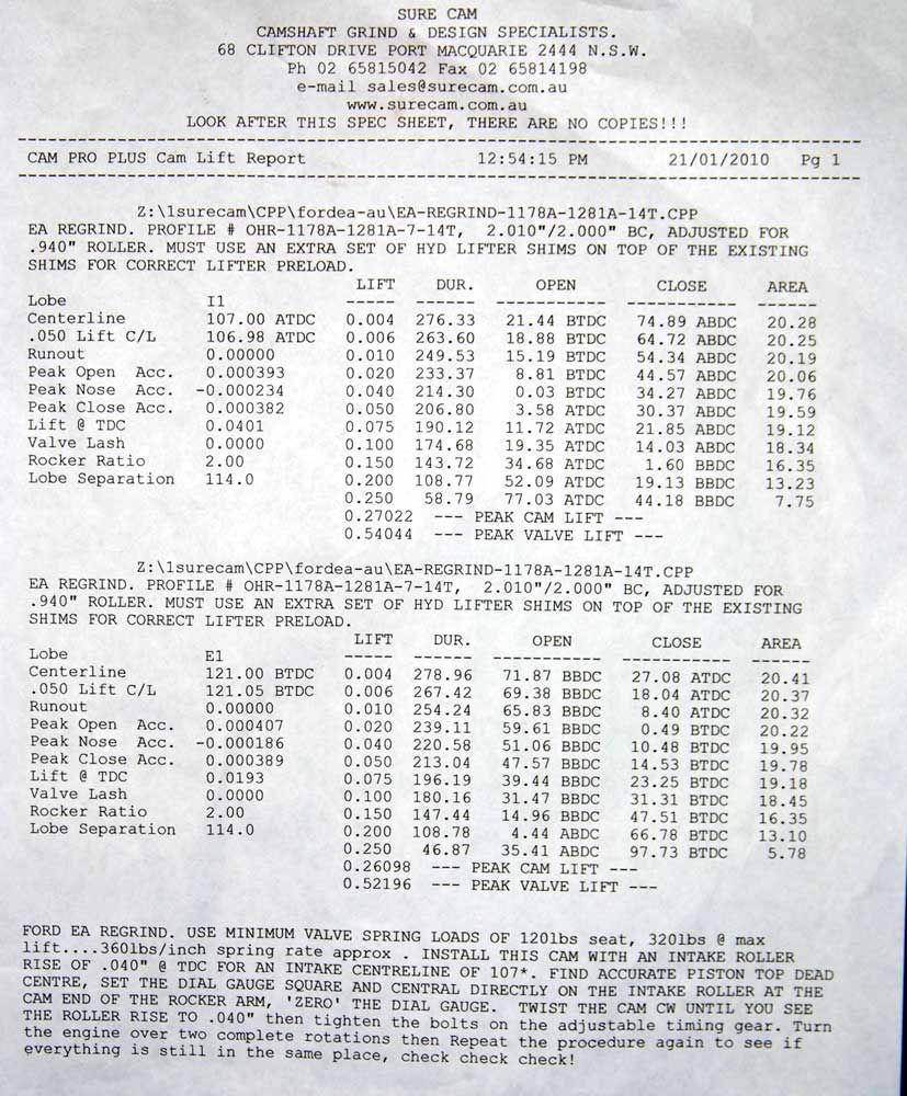
|
|||
| Top | |
|||
| 66 coupe |
|
||
|
that cam is 213 @ 050,
the 276 spec is at 004. |
||
| Top | |
||
| tickford_6 |
|
||
Posts: 6449 Joined: 11th Nov 2004 |
dsyfer wrote: The bend is what happened when I squished the desired length into the same space as the standard manifold, I'm thinking if I run the throttle bodies at approx 45 degrees I can get it straight without the s bend, just gotta get some decent measurements of the engine bay, got tomorrow off so will work on it then, plus I didn't account for the ram tube length, so the manifold can be slightly smaller as well. Here is the full cam spec sheet: What head are you using? and do you have flow numbers for it? If so, post them up and i can run it through engine analyzer pro 3.5 for you. |
||
| Top | |
||
| dsyfer |
|
|||
|
tickford_6 wrote: dsyfer wrote: What head are you using? and do you have flow numbers for it? If so, post them up and i can run it through engine analyzer pro 3.5 for you. Head is not finished yet, I have a 91 & a 94 to play with, any recommendation for valve sizes? I was going to drop past Milton Engine Development today and see what they can do valve wise. I wish my old mate Dave Adams was still around, he was a wizard on ford 6's, his Cortina with a 250 CF ran 9.5 quarters with Nitrous, would love to have seen what he could of done with the SOHC head. |
|||
| Top | |
|||
| Steady ED |
|
|||
|
how about having the TBs right on the flange, and to get the extra length having a gentle bend in the intakes towards the front of the car and up?
could even do them two piece, have the desired bend off the TB, then have a flange for the straight section so you could change length easily.
_________________ ED XR8 Sprint - S-Trim, V500, 249rwkw |
|||
| Top | |
|||
| dsyfer |
|
|||
|
Ok, got some decent measurements of the engine bay today.
Using a 48 x 150mm ram tube 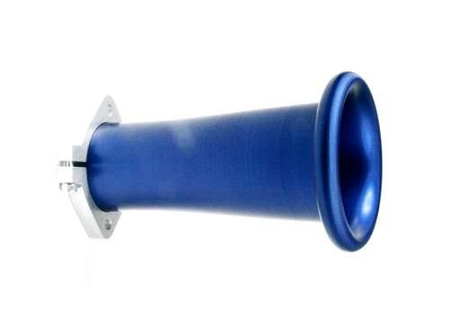 80mm from the valve to the outside of the head, 170mm manifold, Tb and 150mm ram tube ends up with 450mm overall runner length, tubes end over the inner guard, and there would still be room for a airbox, moving the wiper bottle of course. 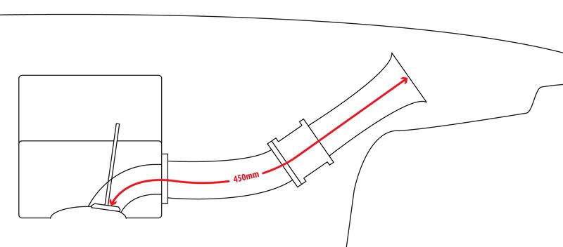 Thoughts on this design guys? |
|||
| Top | |
|||
| Who is online |
|---|
Users browsing this forum: No registered users and 63 guests |


